Extreme ultraviolet photomask and methods and apparatuses for manufacturing the extreme ultraviolet photomask
- Summary
- Abstract
- Description
- Claims
- Application Information
AI Technical Summary
Benefits of technology
Problems solved by technology
Method used
Image

Examples
first embodiment
[0041][Manufacturing Method: A First Embodiment]
[0042]FIG. 5 illustrates a process flow chart of a method of manufacturing a photomask in accordance with a first embodiment. FIGS. 6 through 8 illustrate perspective views of stages in a method of manufacturing a photomask in accordance with the first embodiment.
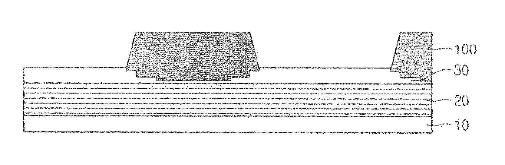
[0043]Referring to FIGS. 5 and 6, in operation S1, a multilayer 20 may be formed on the substrate 10, i.e., a photomask substrate. The substrate 10 may be formed of any suitable material having a low thermal expansion characteristic, e.g., glass. The multilayer 20 may include a plurality of thin films constituting Bragg reflector to improve a reflectance of an extreme ultraviolet radiation used in an extreme ultraviolet exposure system. According to an embodiment, the multilayer 20 may include, e.g., a molybdenum layer and a silicon layer that are alternately stacked. A number of the thin films in the multilayer 20 may be about 40 to about 60. For example, the molybdenum layer...
second embodiment
[0051][Manufacturing Method: A Second Embodiment]
[0052]FIG. 9 illustrates a process flow chart of a method of manufacturing a photomask in accordance with a second embodiment. FIGS. 10 through 14 illustrate perspective views of stages in a method of manufacturing a photomask in accordance with the second embodiment. The second embodiment may be substantially the same as the first embodiment described previously with reference to FIGS. 5-8, with the exception that (i) the upper pattern 45 may be used as a mold to form an absorbing pattern, as opposed to being used as an absorbing pattern, and (ii) the substrate 10 may be rotated during the etching process to form the upper pattern 45.
[0053]In detail, referring to FIGS. 9 and 10, the multilayer 20 may be formed on the substrate 10 (operation S1), and the upper layer 40 may be formed on, e.g., directly on, the multilayer 20 (operation S3). After the mask pattern 50 to pattern the upper pattern 40 is formed on the upper layer 40, the up...
third embodiment
[0070][Manufacturing Method: A Third Embodiment]
[0071]FIG. 15 illustrates a process flow chart of a method of manufacturing a photomask in accordance with a third embodiment. FIG. 16 illustrates a perspective view of a method of manufacturing a photomask in accordance with a third embodiment. The third embodiment may be substantially the same as the second embodiment described previously with reference to FIGS. 9-14, with the exception of a difference in a manufacturing method related to operation S6c of patterning the upper layer 40. Thus, overlapping descriptions will not be repeated.
[0072]Referring to FIGS. 15 and 16, operation S6c of patterning the upper layer 40 may be performed under the condition that position coordinates of the substrate 10 and the second angle (Φ) are fixed and the first angle (θ) continuously varies in the predetermined range. The range for the first angle (θ) may be selected considering the required product characteristic. According to the third embodimen...
PUM
| Property | Measurement | Unit |
|---|---|---|
| Angle | aaaaa | aaaaa |
| Angle | aaaaa | aaaaa |
| Thickness | aaaaa | aaaaa |
Abstract
Description
Claims
Application Information
 - Generate Ideas
- Intellectual Property
- Life Sciences
- Materials
- Tech Scout
- Unparalleled Data Quality
- Higher Quality Content
- 60% Fewer Hallucinations
Browse by: Latest US Patents, China's latest patents, Technical Efficacy Thesaurus, Application Domain, Technology Topic, Popular Technical Reports.
© 2025 PatSnap. All rights reserved.Legal|Privacy policy|Modern Slavery Act Transparency Statement|Sitemap|About US| Contact US: help@patsnap.com