Electric Vehicle Control

a technology for electric vehicles and control circuits, applied in the direction of motor/generator/converter stoppers, process and machine control, emergency protective circuit arrangements, etc., can solve problems such as external sensors, and achieve the effects of extending battery life, minimizing wear on parts, and reducing power consumption

Inactive Publication Date: 2010-07-01
SNYDER MARK
View PDF21 Cites 34 Cited by
  • Summary
  • Abstract
  • Description
  • Claims
  • Application Information

AI Technical Summary

Benefits of technology

[0026]The data described above may also be used to select the most efficient transmission gear for regenerative braking. For example, when the vehicle is descending an incline, based on operator commands, a transmission gear may be selected to maintain optimal motor RPM for battery recharging and minimizing wear on parts consistent with operator commands to accelerate, decelerate, or maintain present speed.
[0027]The present invention addresses the above and other needs by providing a method for controlling an electric vehicle which includes computing an electric motor RPM based on a computed Back Electromotive Force (BEMF). Modern electric vehicle designs inc

Problems solved by technology

Various methods are available for obtaining motor RPM, but most requir

Method used


Image

  • Electric Vehicle Control
  • Electric Vehicle Control
  • Electric Vehicle Control

Examples


Embodiment Construction

[0049]The following description is of the best mode presently contemplated for carrying out the invention. This description is not to be taken in a limiting sense, but is made merely for the purpose of describing one or more preferred embodiments of the invention. The scope of the invention should be determined with reference to the claims.

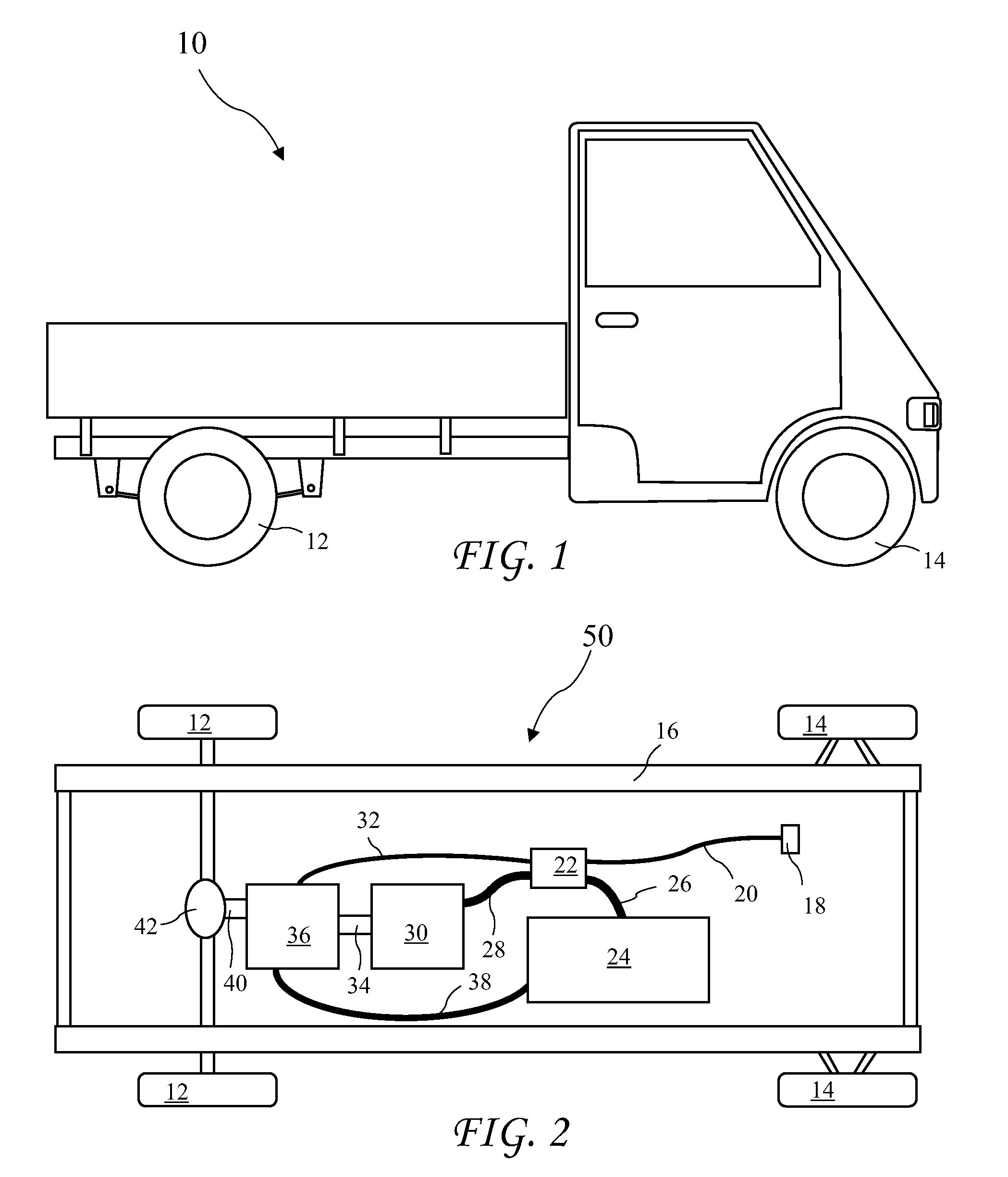
[0050]An electric vehicle 10 suitable for application of the present invention is shown in FIG. 1 and a drivetrain 50 according to the present invention and suitable for use in the vehicle 10 is shown in FIG. 2. The drivetrain 50 includes a drive shaft 40 and an axle 42 connected to drive wheels 12 for driving the vehicle 10. Operator controls 18 are used by an operator to control the driving force provided by the wheels 12. The controls 18 may be foot control, hand controls, or any form of control useable by an operator. In an instance of a remotely controlled vehicle 10, the controls 18 may be a signal receiver. The controls 18 are connected by ...


PUM


Abstract

A method for controlling an electric vehicle includes computing an electric motor RPM based on a computed Back Electromotive Force (BEMF). Modern electric vehicle designs include intelligent control of the electric motors and transmissions to respond to operator controls and provide efficient operation to extend battery life. An accurate measure of motor RPM is required for such control. Various methods are available for obtaining motor RPM, but most require external sensors susceptible to damage from road debris and the like. The BEMF is proportional to motor speed and independent of motor load. The BEMF may further be computed from the difference between IR loss and motor voltage. The motor RPM is them computed from BEMF using data recorded for the individual motor.

Description

[0001]The present application claims the priority of U.S. Provisional Patent Application Ser. No. 61 / 142,103 filed Dec. 31, 2008, U.S. Provisional Patent Application Ser. No. 61 / 142,099 filed Dec. 31, 2008, and U.S. Provisional Patent Application Ser. No. 61 / 142,090 filed Dec. 31, 2008 which applications are incorporated in its entirety herein by reference.BACKGROUND OF THE INVENTION[0002]The present invention relates to electric vehicles and in particular to a electronic systems and methods for control of the vehicle.[0003]Due to the basic characteristics of electric motors, it is beneficial for electric vehicles to be fitted with at least some form of multi-speed, automatic transmission which selects shift points to operate the electric motor or motors in a predetermined RPM range. The multi-speed transmission is very important because it is very inefficient to achieve enough torque from a cost effective drive system to accelerate quickly or climb a steep grade when a vehicle is o...

Claims


Application Information

Patent Timeline
IPC IPC(8): G06F19/00H02P6/08
CPCB60L15/2009Y02T10/72B60L2240/18B60W2520/105B60W2520/125F16H59/48F16H59/66F16H61/0213H02P6/182Y02T10/644Y02T10/646F16H2059/663Y02T10/7275Y02T10/645B60L2240/16Y02T10/64
Inventor SNYDER, MARK
Owner SNYDER MARK
Why Eureka
Try Eureka