Lock releasing mechanism

Inactive Publication Date: 2010-07-08
TOYOTA BOSHOKU KK
View PDF3 Cites 8 Cited by
  • Summary
  • Abstract
  • Description
  • Claims
  • Application Information

AI Technical Summary

Benefits of technology

[0016]The lock releasing mechanism according to the present invention is configured to allow the passage of the current to the motor not only via the current passage circuit of the main switch, but also the parallel circuit in which the limit switch is disposed. The current passing state to the motor is retained by the limit switch while the reciprocating member makes one reciprocating motion. Accordingly, an independent power source supply via the limit switch is ensured without being affected by the current passing and current blocking operation via the main switch only when the motor is activated by performing the current passing operation via the main switch once. Therefore, granted that the current passing operation via the main switch is stopped immediately, the lock releasing mechanism can be continuously in action while the reciprocating member makes one reciprocating motion. Therefore, it is not necessary to continuously push the main switch until the locking mechanism is brought into the unlocked state. Since the mechanism as described thus far includes the conversion gear mechanism configured to convert the direction of rotation output of the motor and the converting means configured to convert the conversion output of the conversion gear mechanism into the reciprocating linear motion of the reciprocating member after having employed the motor as the driving means, the above described advantages are achieved in a simple configuration. In addition, since the reciprocating member is retained for the predetermined period at the full-stroke position during one reciprocating motion of the reciprocating member, the locking mechanism can be reliably unlocked only by the one-push operation of the main switch and, furthermore, the unlocked state of the locking mechanism can be retained for the predetermined period.
[0017]If the converting means includes a pressing projection having the outer peripheral surface formed in the arcuate shape and the receiving portion, and the reciprocating member is retained at the full-stroke position for the predetermined period while the arcuate surface of the pressing projection is in sliding contact with the receiving portion, the period of retaining the reciprocating member at the full-stroke position can be easily designed only by adjusting the length of the arcuate surface f the pressing projection adequately. In addition, since the motor is continuously rotated while the reciprocating member is retained at the full-stroke position, an unnecessary load is not applied to the motor.
[0018]If the cam mechanism which performs the current passing and current blocking operations by coming

Problems solved by technology

In Patent Document 1, the main switch must be pushed continuously until the locked state of the locking mechanism is completely released, so that the operation of the locking mechanism is complicated.
In this configuration, since the power source is continuously supplied to the motor while the swing gear is retained at the full-stroke position, an unnecessary load is applied to the motor, so that there is apprehension that the motor is subjected to damages or early deterioration.
Suppose it is possible, increase in complexity of the mechanism is inevitable.
This specifically presents a problem in a locking mechan

Method used


Image

  • Lock releasing mechanism
  • Lock releasing mechanism
  • Lock releasing mechanism

Examples


Example

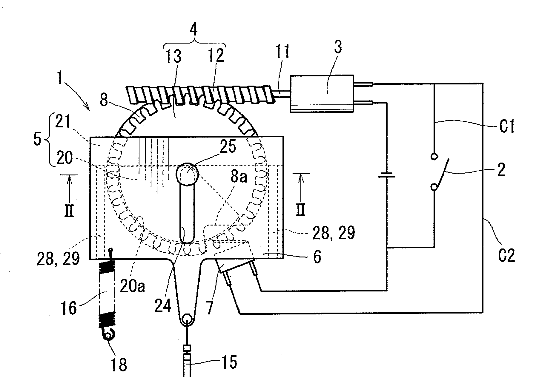
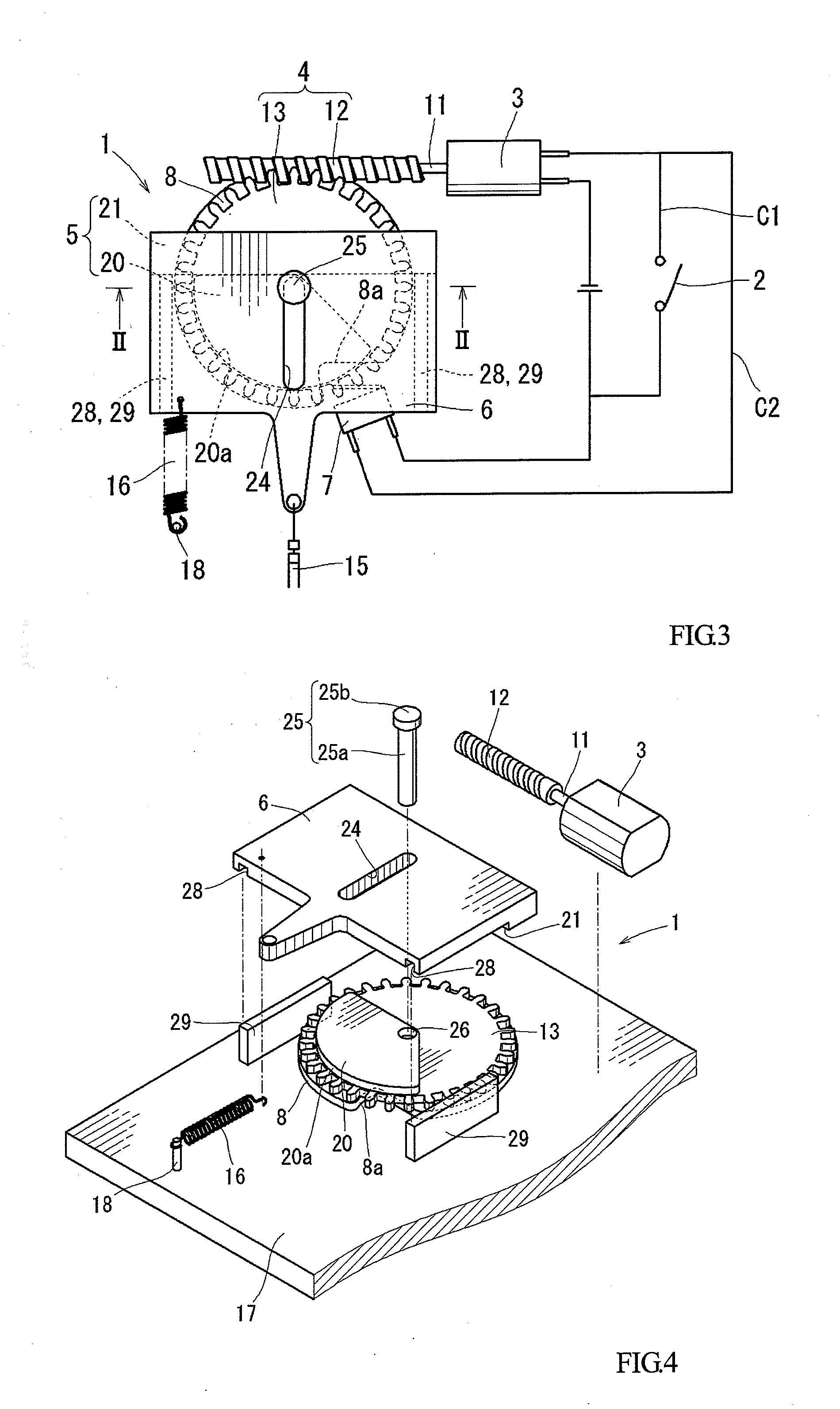
[0045]A first embodiment of the lock releasing mechanism 1 is shown in FIG. 3 to FIG. 9. The lock releasing mechanism 1 may be an lock releasing mechanism by being constructed within a casing formed into a predetermined shape, or may be constructed directly on a board member such as the power seat. In this specification, these members are not specifically discriminated, and the bottom surface of the casing or the board member is shown as a substrate. In this specification or the drawings, the description and illustration are given in a state in which the lock releasing mechanism 1 is constructed on the substrate arranged horizontally. However, the lock releasing mechanism is not limited thereto, and the lock releasing mechanism 1 may be constructed on a side surface of the substrate arranged vertically or obliquely, or may be constructed on a lower surface of the horizontal substrate. In other words, it is also possible to be mounted on a vehicle seat or the like in a state of upsid...

Example

Second Embodiment

[0056]FIG. 11 to FIG. 14 show a second embodiment. The second embodiment is an example in which converting means, that is, pressing means and receiving means are modified. More specifically, as shown in FIG. 11, which is a plan view showing the initial state of the lock releasing mechanism 1 according to the second embodiment, in which a pressing projection 30 by itself is formed into an arcuate shape having a certain length in the circumferential direction, and the outer peripheral surface thereof in the radial direction is formed into an arcuate surface 30a. The point that the radius of curvature thereof is the same as the base gear 13 is the same as the arcuate surface 20a in the first embodiment. In contrast, a receiving projection 31 which comes into abutment with the pressing projection 30 is formed on the lower surface of the slider 6 as a deviated position so as to project in an elongated strip shape.

[0057]The lock releasing mechanism 1 according to the seco...

Example

Third Embodiment

[0058]In the first embodiment or the second embodiment, the worm gear 12 and the base gear 13 of the motor 3 are meshed directly with each other. However, one or a plurality of transmission gears may be interposed between the worm gear 12 and the base gear 13 in order to change the rotating speed of the base gear 13. FIG. 15 shows a third embodiment as an example of the lock releasing mechanism 1 in which the transmission gear is interposed between the worm gear 12 and the base gear 13. In the third embodiment, the rotating speed of the base gear 13 is reduced by interposing two first and second transmission gears 41, 42 between the worm gear 12 and the base gear 13. More specifically, the worm gear 12 and a large diameter portion 41a of the first transmission gear 41 mesh with each other, a small diameter portion 41b of the first transmission gear 41 and a large diameter portion 42a of the second transmission gear 42 mesh with each other, and a small diameter portio...


PUM


Abstract

There is provided an lock releasing mechanism coupled to a locking mechanism via a cable and configured to be capable of releasing a locked state of the locking mechanism by electrically towing the cable, and an lock releasing mechanism can include a main switch configured to operate manually, a motor configured to be driven by a current passing operation via the main switch, a conversion gear mechanism configured to convert the direction of output of the motor, converting means configured to convert a rotating motion to a reciprocating linear motion, a slider to which the cable is coupled and configured to perform the reciprocating linear motion, and a limit switch configured to be able to pass a current to the motor by a parallel circuit different from a current passage circuit of the main switch. The limit switch is in a current blocking state when the slider is at a neutral position. In contrast, a current passing state is retained while the slider makes one reciprocating motion, and the slider is retained at a full-stroke position for a predetermined period.

Description

TECHNICAL FIELD[0001]The present invention relates to an lock releasing mechanism being coupled to a locking mechanism via a coupling member and being capable of releasing a locked state of the locking mechanism by electrically towing the coupling member.BACKGROUND ART[0002]As one of the lock releasing mechanisms as described above, there are those disclosed in Patent Document 1 (JP-A-7-208008) and Patent Document 2 (JP-A-2001-266). Strictly speaking, Patent Document 1 is a mechanism which is operated when locking the locking mechanism, but the description will be given assuming that the mechanism is used as an lock releasing mechanism. In Patent Document 1, a main switch, a motor configured to rotate by an current passing operation by the main switch, a conversion gear mechanism configured to convert the direction of rotation output of the motor, converting means configured to convert the rotating motion to the reciprocal swinging motion, a reciprocating member configured to recipr...

Claims


Application Information

Patent Timeline
IPC IPC(8): F16H25/14B60N2/90
CPCB60N2/0232B60N2/2231B60N2002/0272B60N2/236Y10T74/18296B60N2/0272B60N2/02246
Inventor HARAGUCHI, DAIKISHINODA, SHOEIOKUDA, SHINJI
Owner TOYOTA BOSHOKU KK
Why Eureka
Try Eureka