Rotor of permanent-magnet-type rotating electrical machine

a rotating electrical machine and permanent magnet technology, applied in the direction of magnetic circuits, dynamo-electric machines, electrical apparatus, etc., can solve the problems of reducing the output and efficiency of the permanent magnet rotating electrical machine in a low-speed zone, increasing iron loss, and deteriorating efficiency, so as to improve efficiency, reliability, and productivity. , the effect of high torqu

Active Publication Date: 2010-07-08
KK TOSHIBA
View PDF14 Cites 40 Cited by
  • Summary
  • Abstract
  • Description
  • Claims
  • Application Information

AI Technical Summary

Benefits of technology

[0019]The rotor of a permanent-magnet-type rotating electrical machine of the present invention can realize, when assembled in a stator, a variable-speed operation in a wide range from low speed to high speed. The permanent-magnet-type rotat...

Problems solved by technology

The voltage induced by the permanent magnet is applied to electronic parts of an inverter, and if the applied voltage exceeds a withstand voltage of the electronic parts, the parts will cause insulation breakage.
Such a design, however, lowers the output and efficiency of the permanent-magnet-type rotating electrical machine in a low-speed zone.
In the flux-weakening control, however, since a negative d-axis current that contributes nothing to an output is continuously passed, an iron loss increases to deteriorate efficiency.
Such a voltage increase limits a voltage reduction achieved by the flux-weakening ...

Method used


Image

  • Rotor of permanent-magnet-type rotating electrical machine
  • Rotor of permanent-magnet-type rotating electrical machine
  • Rotor of permanent-magnet-type rotating electrical machine

Examples


first embodiment

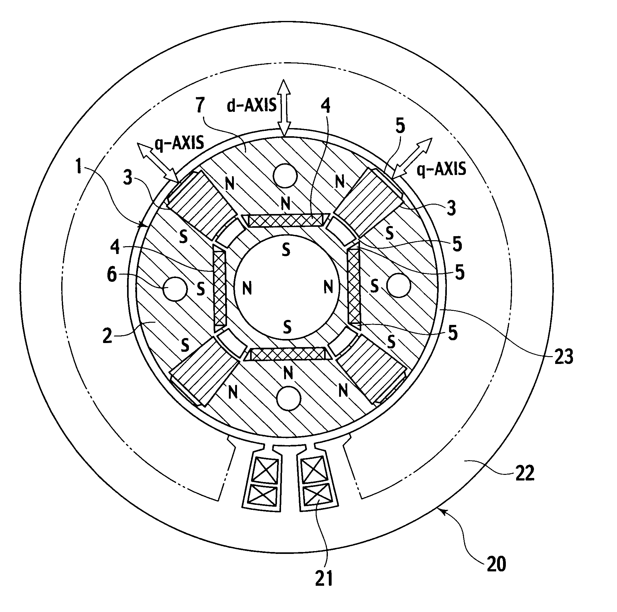
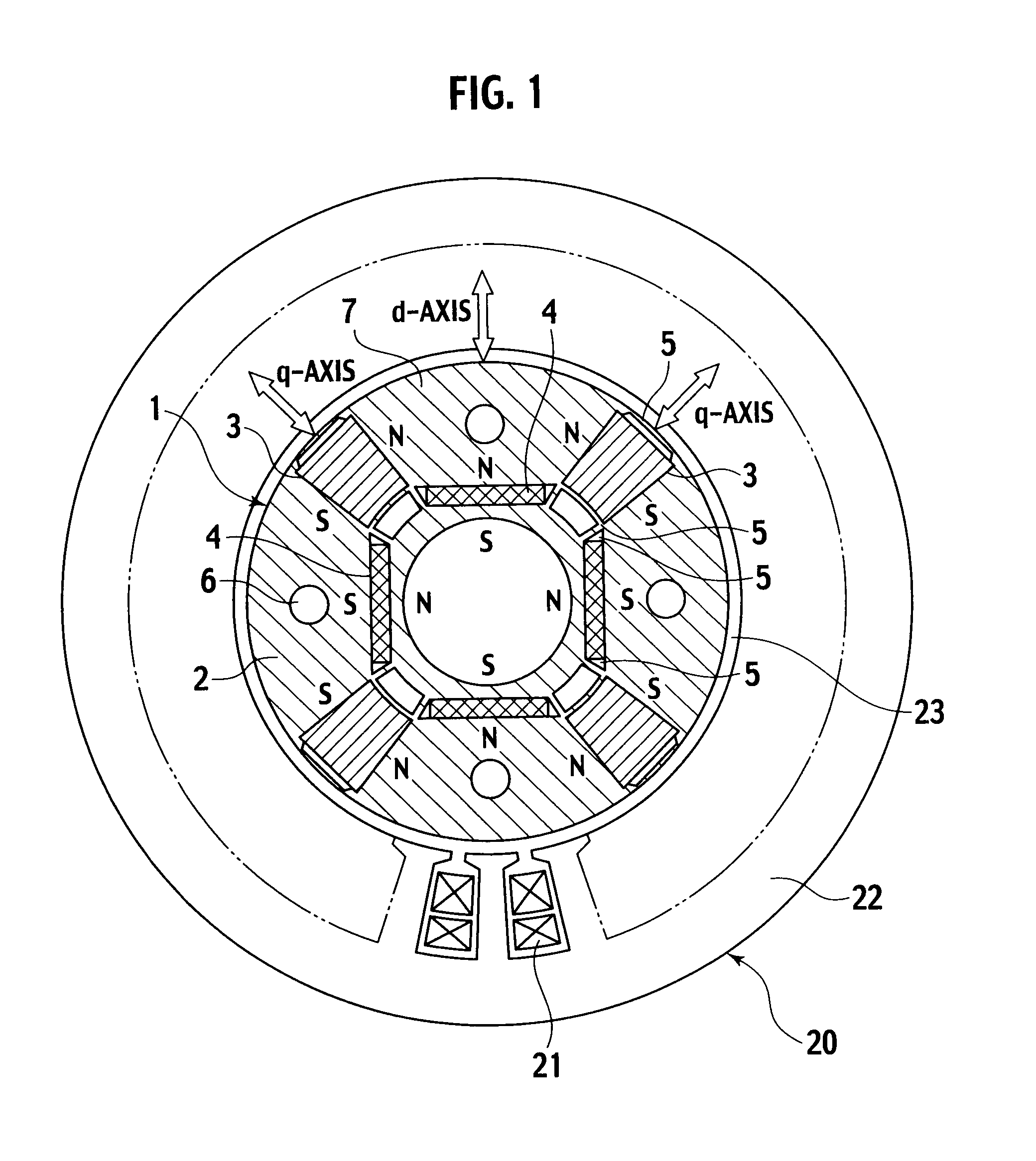
[0030]A permanent-magnet-type rotating electrical machine according to the first embodiment of the present invention will be explained with reference to FIGS. 1 to 5. FIG. 1 shows a structure of the permanent-magnet-type rotating electrical machine according to the embodiment. Inside a stator 20, a rotor 1 is accommodated to face the stator 20 with an air gap 23 interposing between them. The stator 20 may be of a standard structure adoptable for an AC motor. According to this embodiment, the stator 20 is similar to the conventional stator 20 shown in FIG. 9.

[0031]The rotor 1 according to the embodiment includes a rotor core 2, first permanent magnets 3 whose product of a coercive force and a magnetizing direction thickness is small, and second permanent magnets 4 whose product of a coercive force and a magnetizing direction thickness is large. The rotor core 2 is constituted by laminating silicon steel plates. The first and second permanent magnets 3 and 4 are embedded in the rotor ...

second embodiment

[0061]A permanent-magnet-type rotating electrical machine according to the second embodiment of the present invention is characterized in that it adopts an NdFeB magnet having little Dy element in place of the second permanent magnet 4 whose product of a coercive force and a magnetizing direction thickness is large of the permanent-magnet-type rotating electrical machine of the first embodiment shown in FIG. 1. The remaining configuration of the second embodiment is common to the first embodiment shown in FIG. 1.

[0062]With little Dy element, the remanent flux density of the permanent magnet becomes high to 1.33 T or over at 20° C.

[0063]At high speed, the rotating electrical machine of the related art carries out flux-weakening control with a negative d-axis current to suppress a voltage increase due to an induced voltage. At this time, an excessive counter magnetic field acts on a permanent magnet so that the permanent magnet is irreversibly demagnetized to greatly reduce output. To...

third embodiment

[0067]A permanent-magnet-type rotating electrical machine according to the third embodiment of the present invention will be explained with reference to a structural view of a rotor 1 shown in FIG. 6. The permanent-magnet-type rotating electrical machine of this embodiment consists of the rotor 1 shown in FIG. 6 and a stator 20 accommodating the rotor 1. Like the other embodiments, the stator 20 has the configuration shown in FIGS. 1 and 9. In FIG. 6, elements common to those of the first embodiment shown in FIG. 1 are represented with the same reference marks.

[0068]As shown in FIG. 6, the rotor 1 of this embodiment embeds second permanent magnets 4 in a rotor core 2, each second permanent magnet 4 being an NdFeB magnet having an inverted U-shape that protrudes toward an outer circumferential side. A center axis of the inverted U-shape of the second permanent magnet 4 is on a d-axis. Each first permanent magnet 3 is made of an alnico magnet and is arranged inside the rotor core 2 al...


PUM


Abstract

A rotor of a permanent-magnet-type rotating electrical machine of the present invention has a plurality of magnetic poles in point symmetry with respect to a rotation center of a rotor core 2. For each of the magnetic poles, there are arranged a permanent magnet 3 whose product of a coercive force and a magnetizing direction thickness is small and a permanent magnet 4 whose product of a coercive force and a magnetizing direction thickness is large. The permanent magnet 3 whose product of a coercive force and a magnetizing direction thickness is small is irreversibly magnetized by a magnetic field created by a current of an armature coil 21, to change a total linkage flux amount. This realizes a wide-range variable-speed operation of high output, to provide the rotating electrical machine with a wide operating range and high efficiency.

Description

TECHNICAL FIELD[0001]The present invention relates to a rotor of a permanent-magnet-type rotating electrical machine.BACKGROUND TECHNOLOGY[0002]Generally, permanent-magnet-type rotating electrical machines are classified into two types. One is a surface-permanent-magnet-type rotating electrical machine having permanent magnets adhered to an outer circumferential face of a rotor core and an internal-permanent-magnet-type rotating electrical machine having permanent magnets embedded in a rotor core. For a variable-speed drive motor, the latter internal-permanent-magnet-type rotating electrical machine is appropriate.[0003]The latter internal-permanent-magnet-type rotating electrical machine is described in “Design and Control of Internal Magnet Synchronous Motor,” Takeda Yoji, et al., a document of Ohm-sha Publishing (Non-patent Document 1) and Japanese Unexamined Patent Application Publication No. H07-336919 (Patent Document 1). With reference to FIG. 9, a configuration of such a con...

Claims


Application Information

Patent Timeline
IPC IPC(8): H02K21/14
CPCH02K1/2766
Inventor SAKAI, KAZUTOARATA, MASANORI
Owner KK TOSHIBA
Why Eureka
Try Eureka