Anti-Reflection Film

Active Publication Date: 2010-07-08
TOPPAN PRINTING CO LTD
View PDF2 Cites 21 Cited by
  • Summary
  • Abstract
  • Description
  • Claims
  • Application Information

AI Technical Summary

Benefits of technology

[0020]By adopting the configurations described above, it is possible not only to provide an antistatic function and anti-reflection function but also weaken color and unevenness of reflection light. Moreover, in the present invention, the problem whereby blue light leakage occurs during a black display stat

Problems solved by technology

The external light incident to a display surface is reflected on the surface so that a displayed image is interfered with by the reflected image and the quality of display decreases.
While having an advantage of being able to precisely control layer thicknesses of the high and low refractive index sub-layers, dry coating methods have a disadvantage of low productivity for mass production due to a deposition process under vacuum.
Hence, this production method has a problem of collecting dust and the occurrence of errors in a display production caused by charging due to a strong insulation quality
In the method of introducing a conducting agent, there are problems of increasing material cost and hardness decrease of the hard coat layer etc. since a tremendous amount of conducting agent is required to obtain suffic

Method used


Image

  • Anti-Reflection Film
  • Anti-Reflection Film
  • Anti-Reflection Film

Examples


example

Example 1

Transparent Substrate

[0143]80 μm thick triacetyl cellulose films were prepared as the transparent substrates.

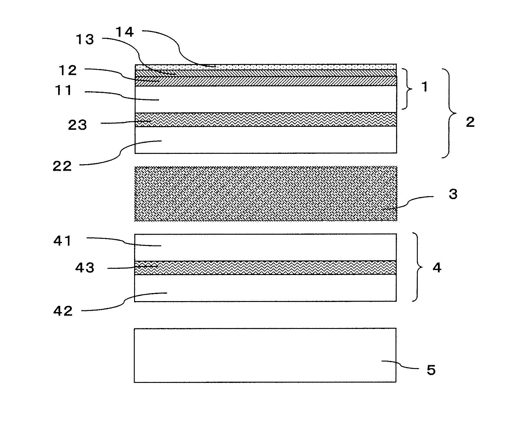
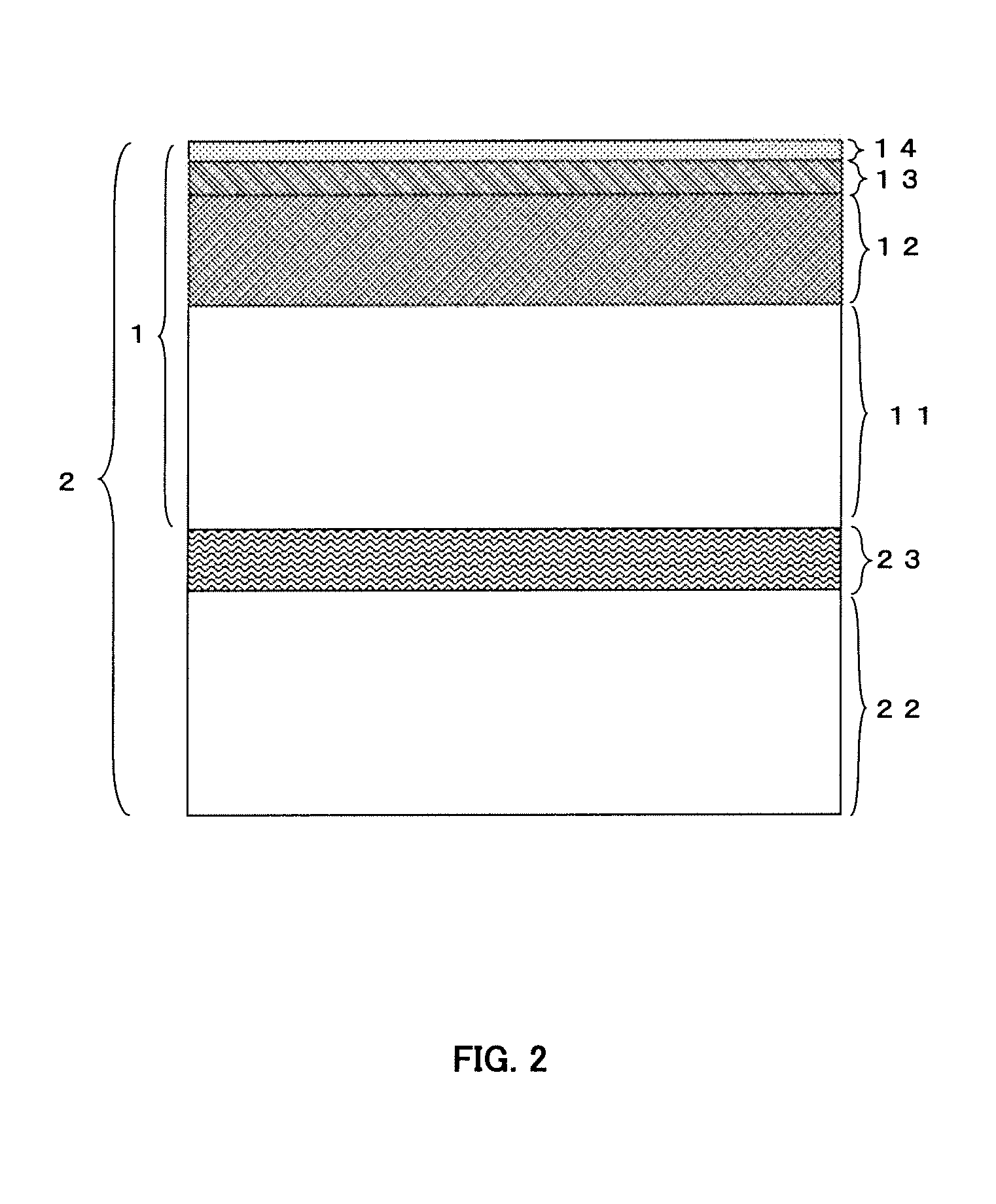
[0144]An (original) polarizing plate was prepared by arranging a polarizing layer of iodine added elongated polyvinyl alcohol between a pair of 80 μm thick triacetyl cellulose films (a first and a second transparent substrates).

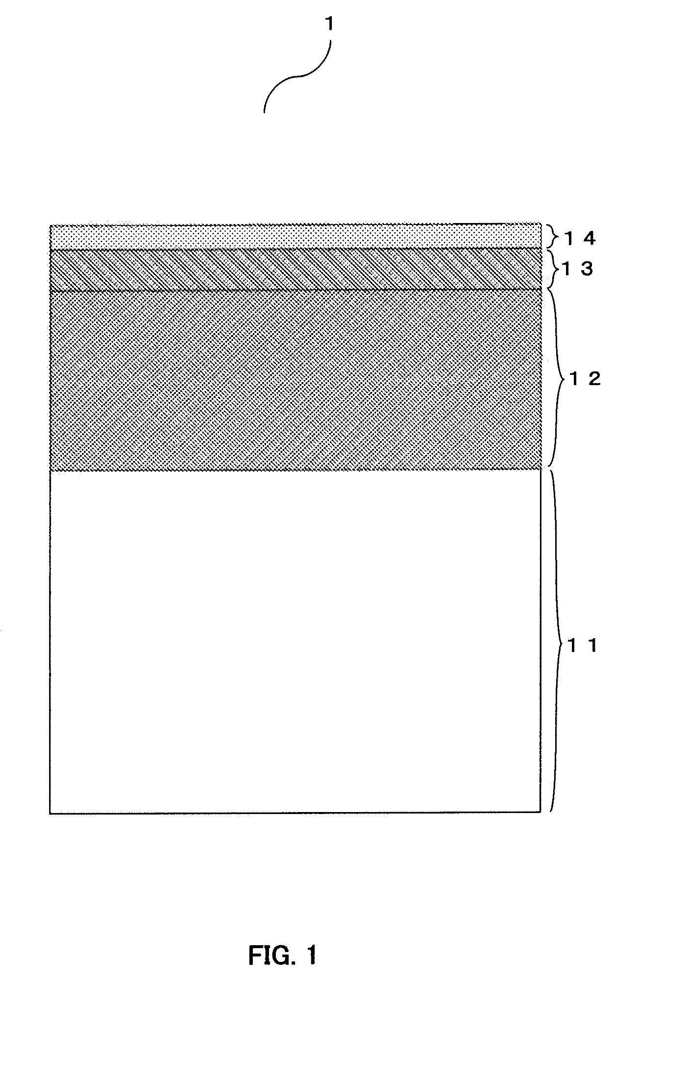
[0145]10 parts by weight of dipentaerythritol triacrylate, 10 parts by weight of pentaerythritol tetraacrylate and 30 parts by weight of urethane acrylate (UA 306T by Kyoeisha chemical Co., Ltd.) as the ionizing radiation curable material, 2.5 parts by weight of Irgacure 184 (by Ciba Japan) as the photopolymerization initiator, and 25 parts by weight of methyl ethyl ketone and 25 parts by weight of butyl acetate were blended together to prepare a coating liquid for forming a hard coat layer. The coating liquid for forming a hard coat layer was coated on a surface of the polarizing plate (on first polarizing plate) and on a transparent substrat...

example 2

Transparent Substrate

[0149]Similar to the case of >, 80 μm thick triacetyl cellulose films were prepared as the transparent substrates.

[0150]Similar to the case of >, an (original) polarizing plate was prepared by arranging an iodine-added elongated polyvinyl alcohol as a polarizing layer between a pair of 80 μm thick triacetyl cellulose films (as a first and a second transparent substrates).

[0151]Similar to the case of >, hard coat layers were formed on a surface of the polarizing plate (on the first polarizing plate) and on a transparent substrate of triacetyl cellulose film. The resultant hard coat layers had a thickness of 5 μm and refractive index of 1.52.

[0152]Similar to the case of >, antistatic layers were formed onto the hard coat layers formed on a surface of the polarizing plate (on the first polarizing plate) and on a transparent substrate of triacetyl cellulose film, respectively. The antistatic layers had a thickness of 163 nm, refractive index of 1.53 and thus an opti...

example 3

Transparent Substrate

[0155]Similar to the case of >, 80 μm thick triacetyl cellulose films were prepared as the transparent substrates.

[0156]Similar to the case of >, an (original) polarizing plate was prepared by arranging an iodine-added elongated polyvinyl alcohol as a polarizing layer between a pair of 80 μm thick triacetyl cellulose films (as a first and a second transparent substrates).

[0157]Similar to the case of >, hard coat layers were formed on a surface of the polarizing plate (on the first polarizing plate) and on a transparent substrate of triacetyl cellulose film. The resultant hard coat layers had a thickness of 5 μm and refractive index of 1.52.

[0158]Tetraethoxysilane as an organosilicon compound raw material was added with isopropyl alcohol and 0.1 N hydrochloric acid and hydrolyzed to obtain a solution containing tetraethoxysilane polymer. This solution was mixed with a dispersion solution of aluminum doped zinc oxide (AZO) particles (solid content ratio: 30% by we...


PUM

PropertyMeasurementUnit
Fractionaaaaaaaaaa
Fractionaaaaaaaaaa
Fractionaaaaaaaaaa

Abstract

The present invention provides an anti-reflection film which weakens color in reflection light and prevents an occurrence of color unevenness. The anti-reflection film has a value in the range of 0.5-1.5% as an average luminous reflectance, a value in the range of 0.2-0.9% as a difference between the maximum and the minimum of spectral reflectance in the visible light region, a value in the range of 0.5-3.0% as an absorption loss in average luminous transmittance, a value in the range of 0.5-4.0% as a difference between the maximum and the minimum of absorption losses in light transmittance at all wavelengths within the visible light region, and a magnitude relation of Q450>Q550>Q650, where Q450, Q550 and Q650 is an absorption loss in light transmittance of said anti-reflection film at wavelengths of 450 nm, 550 nm 650 nm.

Description

CROSS REFERENCE TO RELATED APPLICATION[0001]This application is based on and claims the benefit of priority from the Japanese Patent Application number 2009-000654, filed on Jan. 6, 2009, the entire contents of which are incorporated herein by reference.BACKGROUND OF THE INVENTION[0002]1. Field of the Invention[0003]The present invention relates to an anti-reflection film to prevent external light from reflecting on a window or a surface of display devices etc. Specifically, the present invention relates to an anti-reflection film applied on a surface of liquid crystal displays (LCDs) or transmission type LCDs.[0004]2. Description of the Related Art[0005]In general, displays are used under external light whether they are used indoors or outdoors. The external light incident to a display surface is reflected on the surface so that a displayed image is interfered with by the reflected image and the quality of display decreases. Hence, it is necessary to provide a display surface with ...

Claims


Application Information

Patent Timeline
IPC IPC(8): G02B1/11G02B5/30G02F1/1335G02B1/10G02B1/111G02B1/14G02B1/16
CPCG02B1/111G02B5/3033
Inventor YOSHIHARA, TOSHIAKI
Owner TOPPAN PRINTING CO LTD
Why Eureka
Try Eureka