
Method for making a textile coating and textile coating

Inactive Publication Date: 2010-07-08
FIBROLINE FRANCE
View PDF20 Cites 2 Cited by
  • Summary
  • Abstract
  • Description
  • Claims
  • Application Information

AI Technical Summary

Benefits of technology

[0015]The method described above does not employ the formation of any solution and no drying is required. It may be implemented by means of a significantly smaller-sized and less costly installation than an installation handling a latex solution.
[0016]In addition, the above-defined method has the advantage of offering flexibility with respect to the quantity of binder in the textile coating and the location of this binder. This location may be altered by changing the face on which the powdery binder is deposited and / or by adjusting the proportion of this powdery binder deposited on one face of the web, compared with the quantity of powdery binder deposited on the other face of the web. The location of the binder within the web also depends on the residence time of the web between the electrodes, the setting parameters of the field produced by these electrodes, the specific characteristics of the powder and in particular on its granulometry, and on the denier of the web fibres and the density of said web.
[0027]Since the proportion of heat-meltable binder in relation to the fibres is lower in the surface area than in the core, a smaller quantity of binder can be employed without significantly reducing the robustness of the textile coating, which has the advantage of resulting in savings. In addition, a sub-layer such as a coating can cover the lower face of the web. It is easier to make it adhere to the rear face of the web if this rear face contains little binder. In the absence of a sub-layer, the rear face of the web also forms the rear face of the coating.
[0028]The heat-meltable binder is advantageous in that it can be melted again by means of further heating of the textile coating, after which this coating can be shaped by compression between two forming blocks.

Problems solved by technology

Then the whole is subjected to drying, the function of which is to remove the water from this solution until the latex crosslinks, but which involves the drawbacks of requiring sizeable equipment and of being costly.
Latex is non-thermoplastic and its presence in the textile coating is detrimental to recycling of the latter.
Using a latex solution involves other drawbacks than that of requiring a drying phase.
In particular, it entails the pollution of considerable quantities of water the decontamination of which requires a dedicated purification installation, which entails substantial investments and maintenance costs.
In both cases, coating on the underside of the web does not allow satisfactory mechanical properties to be obtained, in particular in terms of dimensional stability and abrasion resistance of the textile coating.

Method used


Image

  • Method for making a textile coating and textile coating
  • Method for making a textile coating and textile coating
  • Method for making a textile coating and textile coating

Examples


example 1

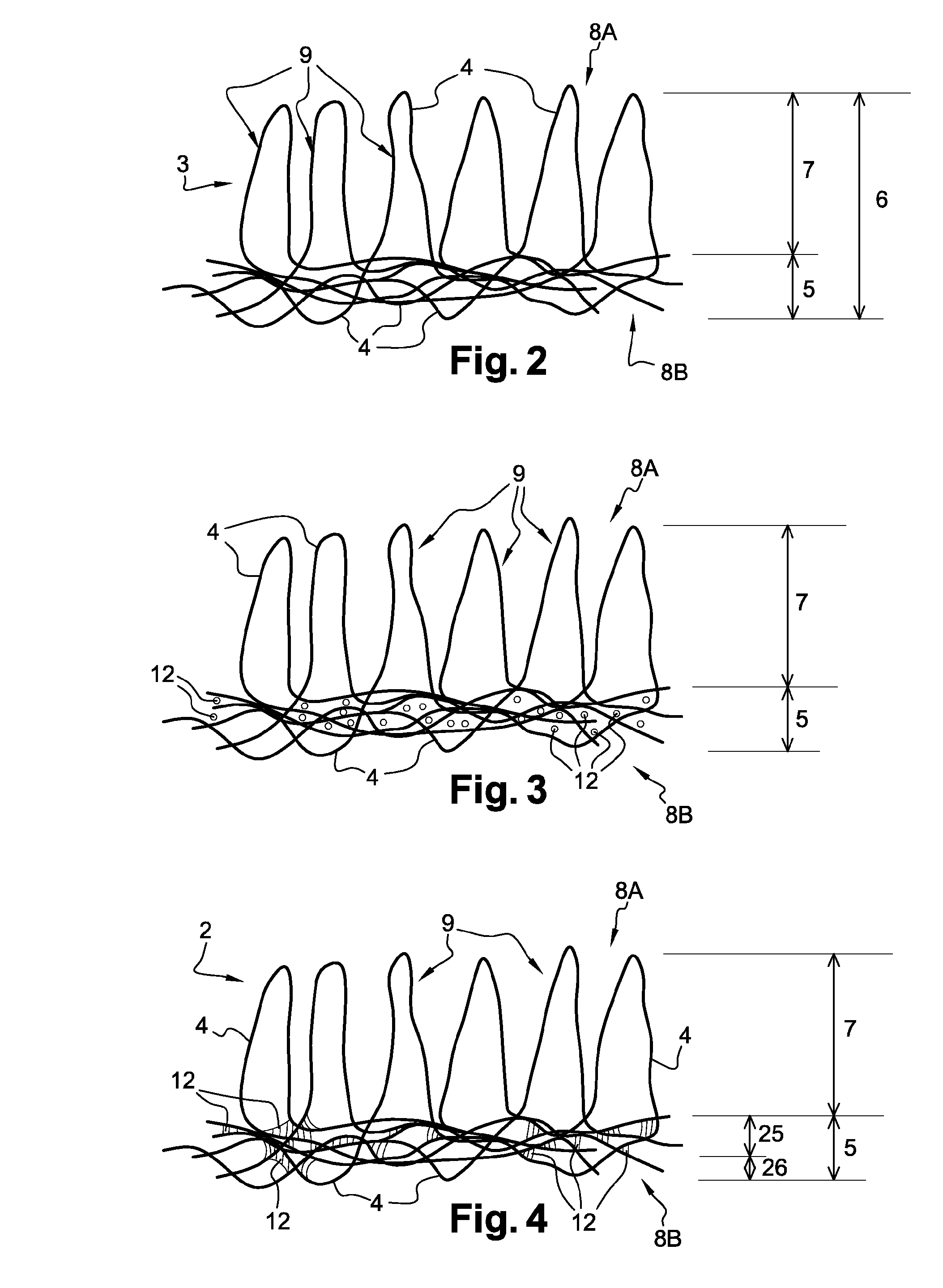
[0049]In this example, the web 3 was a velour needled product weighing 600 g / m2 and having a thickness of approximately 6 mm. It consisted of a mixture of fibres 4 of 6.5 dtex, 17 dtex and 150 dtex, made of polypropylene and initially containing no binder.

[0050]The binder 12 consisted of high-density polyethylene, which was sprinkled at the rate of 90 g / m2 on the web 3. Before being incorporated in this web, it was present in the form of a powder having a granulometry of 0 μm to 80 μm and is commercialized by the company ABIFOR (Wutöschingen—GERMANY) under the reference 1300 / 20.

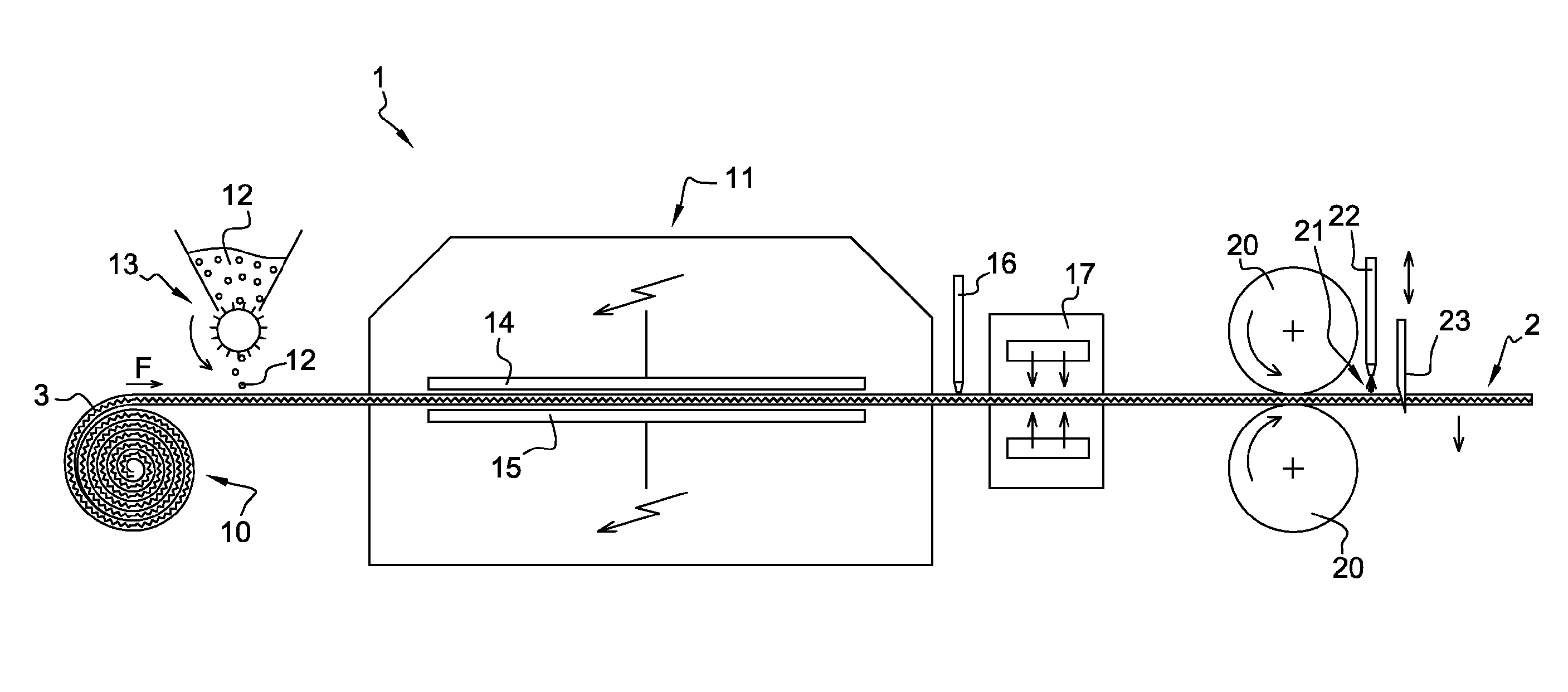
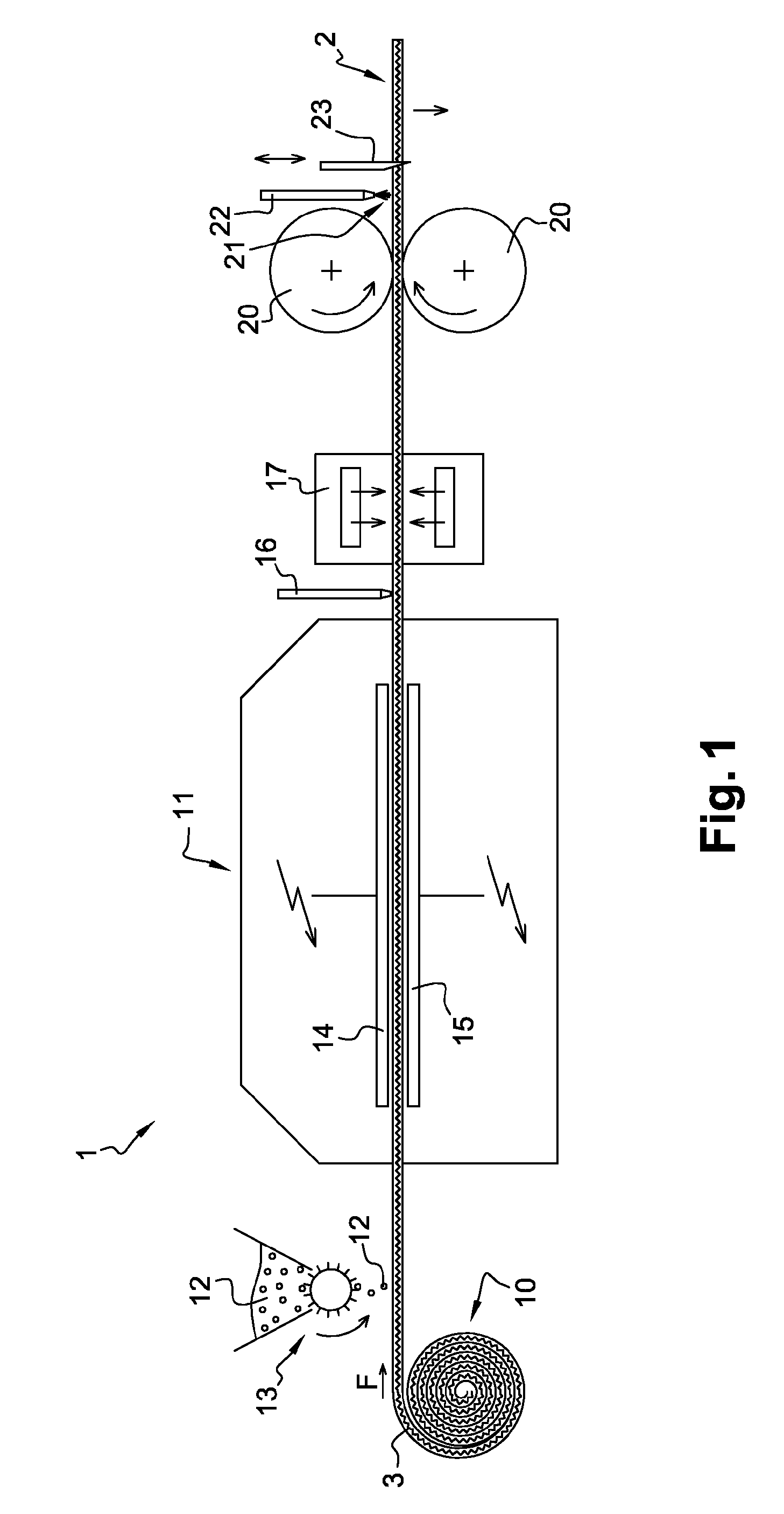
[0051]Impregnation of the web 3 by the powdery binder 12 was carried out in the device 11 fitted with flat electrodes 14 and 15. The alternating electric field produced between these electrodes 14 and 15 had a value of 2 kV / mm and a frequency of 50 Hz. The web 3 containing the powdery binder 12 had an alternating electric field applied to it for 20 sec. It was then placed for more than 2 min. in the oven 17 s...

example 2

[0056]In this example the same web 3 and the same binder 12 were used as in example 1.

[0057]This binder 12 was sprinkled at the rate of 120 g / m2 on the web 3.

[0058]Impregnation of the web 3 by the powdery binder 12 was carried out in the device 11 fitted with flat electrodes 14 and 15. The alternating electric field produced between these electrodes 14 and 15 had a value of 2 kV / mm and a frequency of 50 Hz. The web 3 containing the powdery binder 12 had an alternating electric field applied to it for 20 sec. It was then placed for more than 2 min. in the oven 17 set at a temperature higher than the melting temperature of the binder and lower than the melting temperature of the fibres.

[0059]A carpet 2 obtained according to this example 3 was subjected to the Lisson test as defined by the EN 1963 standard from the year 1997. Following this test, a determination by visual evaluation of the level of defibration of carpet 2 was performed and gave a value of ⅘ in the machine direction, an...

example 3

[0061]In this example, the web 3 was a velour needled non-woven, weighing 550 g / m2. Its fibres 4, which initially did not contain any binder, were made of polyester and had a denier of 6.7 dtex.

[0062]The binder 12 was an epoxy resin, which was sprinkled at the rate of 150 g / m2 on the web 3. Before being incorporated in this web 3, it was present in the form of a powder having a granulometry of 0 μm to 100 μm and is commercialized by the company BAKELITE (GERMANY) under the reference 6171TP.

[0063]Impregnation of the web 3 by the powdery binder 12 was carried out in the device 11 fitted with flat electrodes 14 and 15. The alternating electric field produced between these electrodes 14 and 15 had a value of 3 kV / mm and a frequency of 50 Hz. The web 3 containing the powdery binder 12 had an alternating electric field applied to it for 20 sec. It was then placed for more than 2 min. in the oven 17 set at a temperature higher than the melting temperature of the binder and lower than the m...


PUM

PropertyMeasurementUnit
Thicknessaaaaaaaaaa
Compositionaaaaaaaaaa
Areaaaaaaaaaaa

Abstract

A textile coating is made from a web of fibres including a first area and a second area. The first area is a cohesion area where the fibres of the web are integrated into a tight entanglement holding the fibres and located on only a portion of the thickness of the web. A method for making the textile coating includes: applying an alternating electric field to the web having at least one face bearing a heat-meltable powdery binder, thereby introducing said powdery binder into the web, so as to concentrate the binder at the first area, then melting the binder by supplying heat, and leaving the binder to cure or causing it to cure.

Description

TECHNICAL FIELD[0001]The present invention concerns a method for making a textile coating, and such a textile coating, which may in particular be a floor covering, a wall covering or a trim carpet for the passenger compartment of a vehicle.PRIOR ART[0002]It is known to make textile coverings from a needled fibrous web and in particular from a velour fibrous web, which is a web that has been needled in such a manner that a part of its thickness is formed essentially of joined loops. The fibres of such a loop originate in an area located beneath the loops and in which the fibres are intertwined and thus partially interlinked.[0003]When manufacturing the coating, the back of the velour web is impregnated with an aqueous solution of latex. Then the whole is subjected to drying, the function of which is to remove the water from this solution until the latex crosslinks, but which involves the drawbacks of requiring sizeable equipment and of being costly.[0004]Once drying has been carried ...

Claims


Application Information

Patent Timeline
IPC IPC(8): D04H3/12B32B38/00
CPCD04H1/60D04H3/12D04H11/08D06N3/0084D06N7/0076D06N7/006B05D1/007D06N7/0084B05D3/0272D06N3/0093D06N7/0068Y10T442/60
Inventor BONIN, VINCENTVILLE, JEROME
Owner FIBROLINE FRANCE
Learn More