Multi-Segment Modular Stent And Methods For Manufacturing Stents

a modular stent and multi-segment technology, applied in the field of medical devices, can solve the problems of more exuberant intimal response, intimal trauma, and higher incidence of restenosis, and achieve the effects of reducing frictional motion, constant microtrauma and aseptic inflammatory changes, and reducing the incidence of restenosis

Inactive Publication Date: 2010-07-08
RABKIN DMITRY J +2
View PDF3 Cites 170 Cited by
  • Summary
  • Abstract
  • Description
  • Claims
  • Application Information

AI Technical Summary

Benefits of technology

[0017]Another object of the present invention is to provide a new and improved stent designed to provide optimal radial forces, flexibility and kink resistance for a wide range of clinical applications.
[0039]Finally, in order to facilitate the manufacture and use of multi-segment stents, stent blanks are initially prepared, which may be done even before the desired sequence and arrangement of the Z-rings and closed-cell rings have been determined. A blank is formed by laser-cutting a small diameter tube of shape-memory material to define a plurality of pairs of longitudinally adjacent Z-rings having interconnector portions integrally joining the Z-rings of each pair in a manner such that every pair of adjacent Z-rings constitutes a closed-cell ring. The small diameter tube is then expanded and heat treated to form a stent blank. Once the particular intended application of the stent is known, the particular desired sequence and arrangement of the interconnected closed-cell rings and Z-rings are determined. Certain ones of the interconnector portions are then removed from the blank, either mechanically or using a laser tool, in order to provide the desired arrangement and sequence of the closed-cell rings and Z-rings. This technique enables an inventory of blanks for multi-segment stents to be maintained so that once a particular clinical application is determined for a stent, it is a simple and quick matter to obtain an appropriate stent blank and remove appropriate interconnector portions to provide the stent with optimal features for'the particular application.

Problems solved by technology

In addition, the stent should be maximally apposed to the vessel wall to minimize the relative motion between the vessel wall and the struts from which the stent is constructed, which may result in intimal trauma.
A stent which is not completely apposed to the vessel wall results in more exuberant intimal response and a higher incidence of restenosis.
Poor stent apposition in a pulsating artery may be associated with repetitive micro trauma to the vessel wall, again resulting in an increase in the incidence of clot formation and restenosis.
Some of these designs attempt to address problems which are encountered in clinical practice including inadequate wall apposition, overlapping of neighboring struts and incomplete cell expansion leading to insufficient radial force distribution.
However, the stents described in the prior art generally are specifically designed to provide only one or two of these features and therefore only meet a limited number of the desired objectives.
However, this technique has certain problems and limitations.
One problem is in the manufacture of self expanding stents which are not uniform in design, e.g. multi-segment stents.
However, as a non-uniform multi-segment stent is mechanically expanded, the struts forming the annular rings are subjected to asymmetrical forces resulting in irregular or distorted closed-cell and Z-ring geometry.
This irregular geometry is “memorized” by the stent so that upon delivery to and expansion in a stenosed region of a vessel, it will not provide optimal force distribution or wall apposition.
Another problem arises in the manufacture of stents from a laser slotted tube when it is desired that the tube wall be very thin so that the struts formed from the slotted tube wall are correspondingly thin, such as when the stent is to be expanded in a small diameter vessel.
However, this limits the width of the struts.
Still another problem in the manufacture of non-uniform multi-segment stents comprising a plurality of interconnected closed-cell rings and Z-rings by laser-cutting and then expanding small diameter tubes is that it is often costly and time consuming to create specific software for guiding the laser cutting tool to cut'the particular desired sequence and configuration of closed-cell rings and Z-rings.
The need to create specific laser cutting tool software for a particular predetermined desired sequence and arrangement of closed-cell rings and Z-rings for a stent has impeded the widespread adoption and use of multi-segment stents having annular rings sequenced and arranged to provide optimal characteristics for a particular clinical application.

Method used


Image

  • Multi-Segment Modular Stent And Methods For Manufacturing Stents
  • Multi-Segment Modular Stent And Methods For Manufacturing Stents
  • Multi-Segment Modular Stent And Methods For Manufacturing Stents

Examples


Embodiment Construction

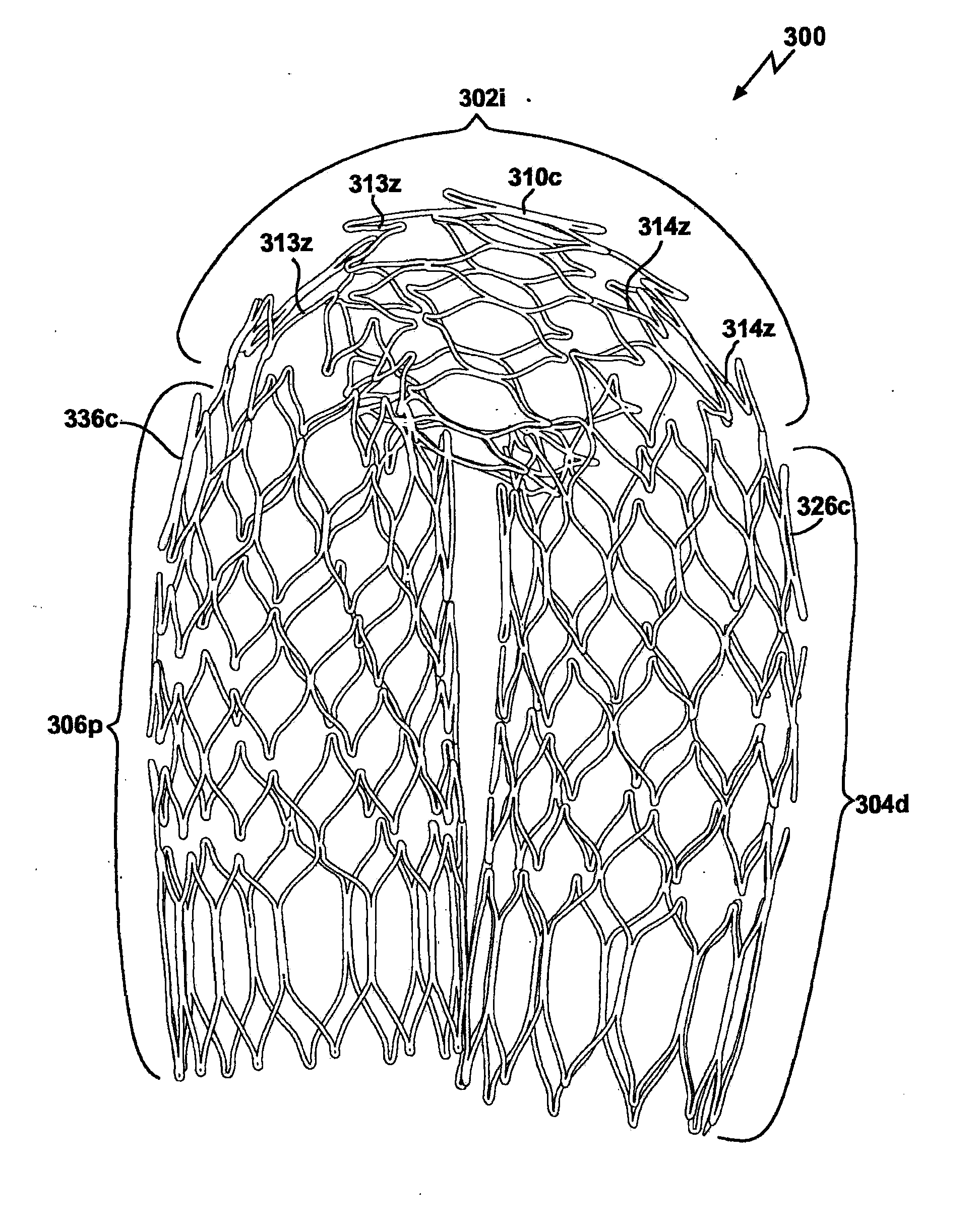
[0081]A stent in accordance with the invention has a modular construction constituted by a combination of interconnected segments of annular Z-rings and closed-cell rings. Each module is formed of three segments including an intermediate segment comprising either a closed-cell segment or a Z-segment and a pair of end segments comprising the other of closed-cell or Z-segments.

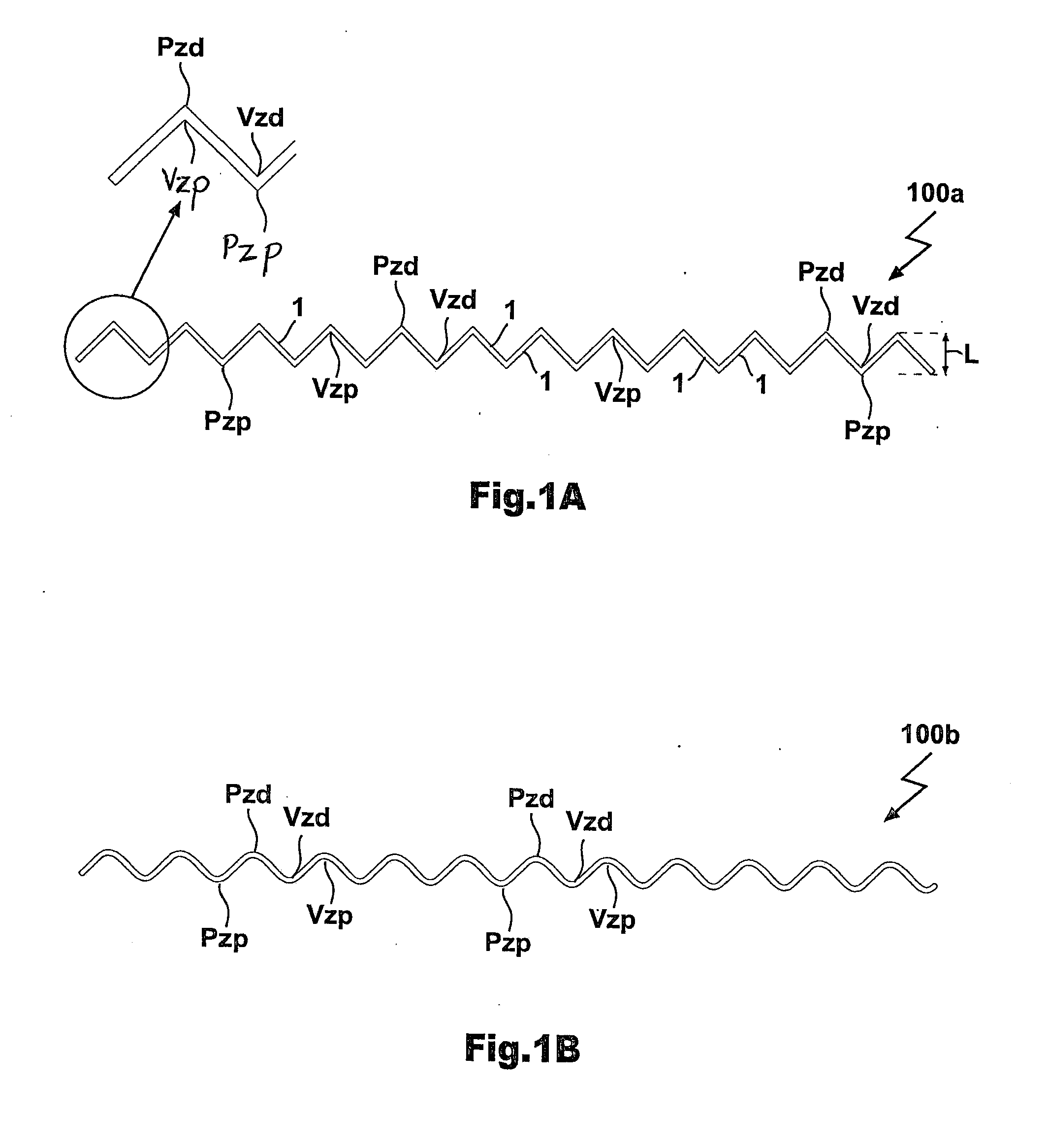
[0082]Referring now to the drawings wherein like reference characters designate identical or corresponding parts throughout the several views, and more particularity to FIG. 1(a), a Z-ring 100a comprises struts 1 which together define a plurality of “Z” or sinusoidal or wave shapes. The struts 1 may be formed by expanding a laser-slotted metallic tube, or from portions of a single wire, or from individual wire elements, or by any other method of construction known to those skilled in the art. The mesh design of the stent can be laser cut from a large diameter tube, which is equal to the final diameter of a fully...


PUM


Abstract

A modular stent comprises at least one stent module including an intermediate segment consisting of one of either a closed-cell segment or a Z-segment and a pair of end segments connected to respective longitudinal ends of said intermediate segment, each end segment consisting of the other of said closed-cell segment or Z-segment, each closed-cell segment consisting solely of at least one annular closed-cell ring and each Z-segment consisting solely of at least one annular Z-ring. A method of manufacturing a stent form a small diameter tube includes laser-cutting the small diameter tube to define a plurality of longitudinally adjacent Z-rings, providing interconnector portions of said tube integrally joining facing aligned or offset Z-rings, expanding the small diameter tube, and removing predetermined interconnector portions from the expanded tube to provide the predetermined desired arrangement of interconnected closed-cell rings and Z-rings.

Description

CROSS-REFERENCE TO RELATED APPLICATIONS[0001]This application is a continuation of co-pending U.S. patent application Ser. No. 12 / 112,712, filed Apr. 30, 2008, which in turn is a continuation of co-pending U.S. patent application Ser. No. 10 / 333,600, filed Jan. 21, 2003, which in turn is a National Phase filing of PCT patent application No. PCT / US2002 / 38456, filed Dec. 3, 2002 and designating the United States, and expired U.S. provisional patent application Ser. No. 60 / 337,060, filed Dec. 3, 2001, all of which are incorporated herein by reference.FIELD OF THE INVENTION[0002]This invention relates generally to medical devices, and more particularly to radially expandable stents for holding vessels such as arteries for open flow, and to methods for manufacturing stents.BACKGROUND OF THE INVENTION[0003]A stent is a generally longitudal cylindrical device formed of biocompatible material, such as metal or plastic, which is used in the treatment of stenosis, strictures, or aneurysms in ...

Claims


Application Information

Patent Timeline
Patent Type & Authority Applications(United States)
IPC IPC(8): A61F2/82A61F2/06
CPCA61F2/91A61F2/915A61F2002/91558A61F2230/0054A61F2002/91575A61F2230/0013A61F2002/91566
Inventor RABKIN, DMITRY J.MORAG, EYALPERELSON, OPHIR
Owner RABKIN DMITRY J
Why Eureka
Try Eureka