Magnetic flux controllable rotating electric machine system

a magnetic flux control and electric machine technology, applied in the direction of rotating magnets, synchronous machines with stationary armatures, windings, etc., can solve the problems of difficult control of electric motors, high-speed rotational regions, and inability to achieve optimal power in a wide rotational speed range, so as to increase the magnetic flux crossing the armature coil, and increase the magnetic resistance

Inactive Publication Date: 2010-07-15
KURA LAB
View PDF10 Cites 18 Cited by
  • Summary
  • Abstract
  • Description
  • Claims
  • Application Information

AI Technical Summary

Benefits of technology

[0021]The field magnet is composed of parallel connection of magnet elements which are different in easiness of magnetization, or includes a permanent magnet whose easiness of magnetization (that is the product of length and coercivity) changes continuously within section thereof. Since magneto-motive force (difference in magnetic potential) is added by the excitation coil to the magnet elements substantially uniformly, the difference in magnetic potential divided by the length becomes strength of magnetic field to be applied to each magnet element, the magnet element with small product of the length and the coercivity is magnetized easily. Therefore, magnetization state of the magnet element which are different in easiness of magnetization is controlled selectively in accordance with the electric current fed to the excitation coil.
[0022]The magnet element has magnetization of one of the first magnetization and the second magnetization which are opposite in direction to each other. The magnet element that magnetizes the magnetic salient poles in the direction opposite to the magnetization direction of the island-shaped magnetic poles is assumed to be the first magnetization, and the amount of magnetic flux crossing the armature coil increases. There...

Problems solved by technology

However, in both electric motors and electric generators, optimum power is not always obtained in a wide rotational speed range because the amount of magnetic flux supplied from field magnet is constant.
In the case of the electric motor, it will become difficult to control the electric motor in a high-speed rotational region because the back electromotive force (power generation voltage) becomes too high, and therefore, various methods for weakening the field strength as field-weakening control have been proposed.
In the case of electric motor, field-weakening control by means of phase leading electric current control has been widely adopted, but the energy efficiency and the control range are limited.
However, this has drawbacks such as that the field magnet is susceptible to the magnetic field of an ...

Method used


Image

  • Magnetic flux controllable rotating electric machine system
  • Magnetic flux controllable rotating electric machine system
  • Magnetic flux controllable rotating electric machine system

Examples


first embodiment

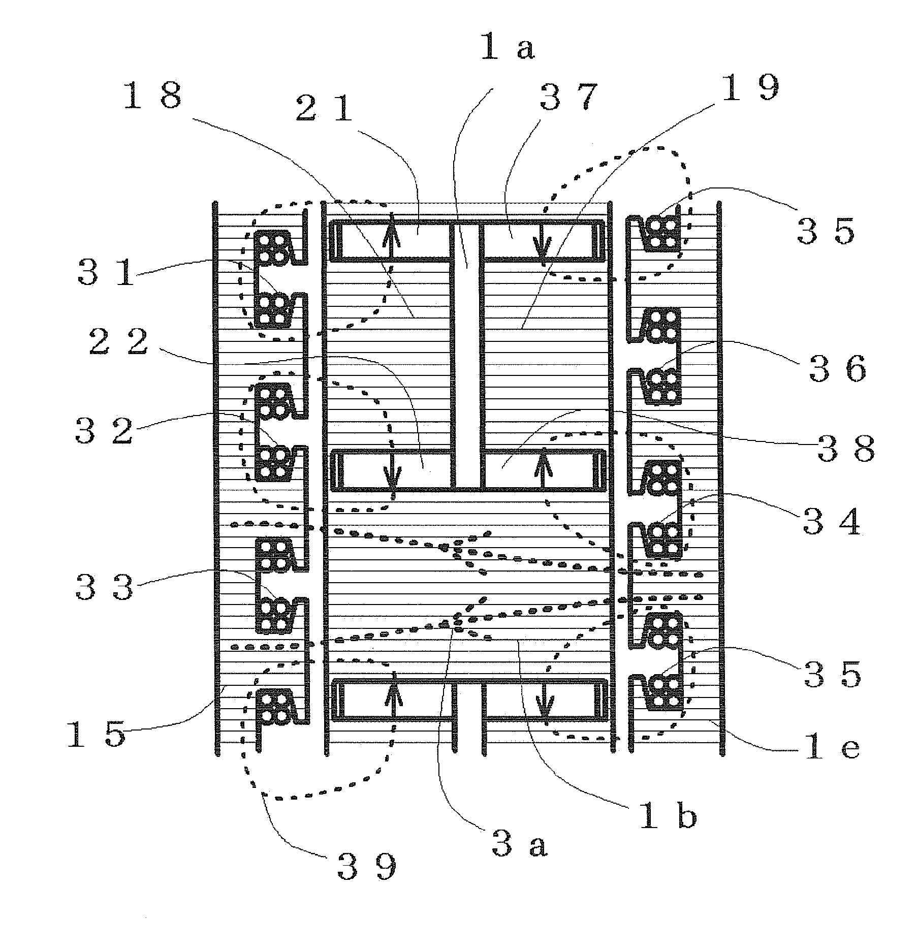
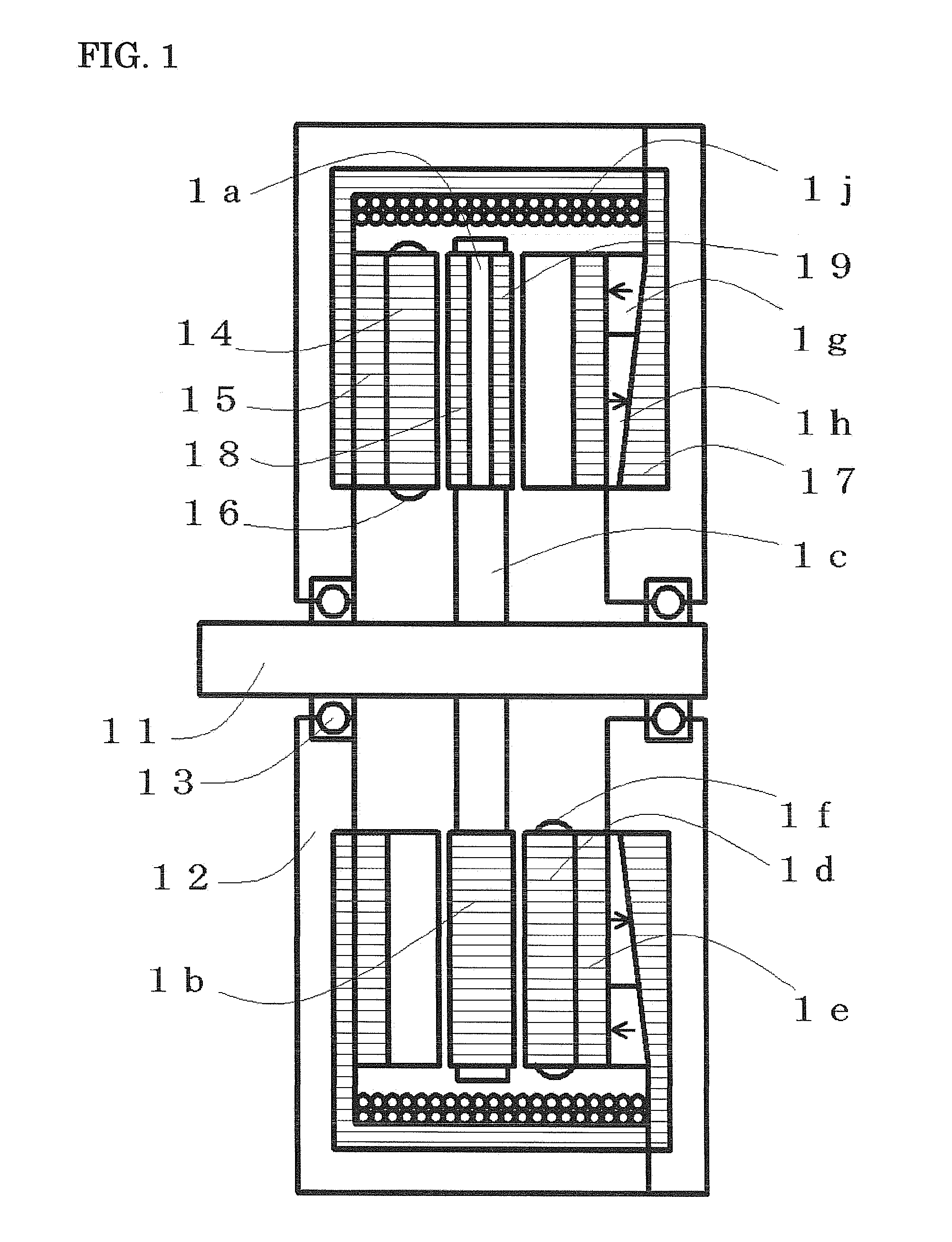
[0097]FIG. 6 shows a longitudinal sectional view of the embodiment in which the present invention is applied to a rotating electric machine apparatus having an axial gap structure, double stators. Although rotor composition is almost the same as the first embodiment shown in FIG. 1, a permanent magnet 62 is disposed between the island-shaped magnetic poles 18 and 19, and a permanent magnet 65 is disposed between the magnetic salient poles 64 and 66. Thickness of the permanent magnet 65 is smaller than that of the permanent magnet 62. Arrows in the permanent magnets 62 and 65 indicate magnetization direction. The permanent magnet magnetizes the island-shaped magnetic poles 18 and 19 while being an isolation member between the island-shaped magnetic poles 18 and 19, the permanent magnet 65 magnetizes the magnetic salient poles 64 and 66 while being an isolation member between the magnetic salient poles 64 and 66.

[0098]As viewed in FIG. 6, the first armature disposed at left side has a...

fourth embodiment

[0184]An armature and a rotor of a rotating electric machine showing a longitudinal section in FIG. 17 are same as the rotating electric machine of the fourth embodiment shown in FIG. 13 except a magnetic excitation part, and the magnetic excitation part is electric current excitation. The magnetic excitation part consists of the cylindrical magnetic core 171 that is an excitation flux path member, the excitation coil 13p wound around the cylindrical magnetic core 171, and both ends of the cylindrical magnetic core 171 face prolonged parts of the circular magnetic substrates 137 and 13c, respectively. Magnetic flux induced by the excitation coil 13p flows through the cylindrical magnetic core 171, the circular magnetic substrate 137, the magnetic salient poles 13a, the magnetic teeth 134, the magnetic salient poles 13f, and the circular magnetic substrate 13c, then flux amount through the armature coil 136 is controlled effectually.

[0185]Although composition of the armature and the ...

third embodiment

[0203]The magnetic excitation part is the same composition as the third embodiment, an excitation path pole 9k faces the magnetic core 239 connecting with a circular magnetic substrate of the first rotor 234 through a minute gap, an excitation path pole 9m faces the magnetic core 23a connecting with a circular magnetic substrate of the second rotor 238 through a minute gap. The cylindrical first magnet element 9p and the second magnet element 9n are arranged between the cylindrical excitation path poles 9k and 9m, the excitation coil 9q is arranged so that magnetic flux may be induced in closed magnetic path constituted from the excitation path pole 9m, the first magnet element 9p, the excitation path pole 9k, and the second magnet element 9n. Number 9r indicates a conductor layer.

[0204]Magnetic flux coming from the magnetic excitation part is supplied between the circular magnetic substrate of the first rotor 234 disposed at the left end, and the circular magnetic substrate of the ...


PUM


Abstract

A rotor surface has magnetic salient poles and island-shaped magnetic poles alternately in circumferential direction, and the island-shaped magnetic pole is constituted so that a magnetic flux coming from an external source does not flow through. A magnetic excitation part magnetizes the island-shaped magnetic poles and the magnetic salient poles collectively in the same direction, and then control a flux amount flowing through an armature. The armature has armature coils that face the magnetic salient pole and the island-shaped magnetic pole simultaneously so that driving torque fluctuation or power generation voltage waveform distortion is controlled. The magnetic excitation part changes magnetization state of a field magnet irreversibly, or changes an excitation current to an excitation coil to control a flux flowing through the armature.

Description

CROSS-REFERENCE TO RELATED APPLICATIONS[0001]The present application claims priority under 35 U.S.C. §119 to Japanese Patent Applications No. 2009-5444 filed Jan. 14, 2009, No. 2009-21101 filed Feb. 2, 2009, No. 2009-48940 filed Mar. 3, 2009 and No. 2009-109130 filed Apr. 28, 2009. The contents of these applications are incorporated herein by reference in their entirety.BACKGROUND OF THE INVENTION[0002]1. Field of the Invention[0003]The present invention relates to axial gap rotating electric machines such as electric generators and electric motors having a permanent magnet.[0004]2. Discussion of the Background[0005]Rotating electric machine apparatus, such as an electric generator for electromagnetically generating electric power by relative rotation of a permanent magnet and an armature, or an electric motor for generating relative rotation between a permanent magnet and an armature by interaction of the permanent magnet and a magnetic field generated by electric current supplied ...

Claims


Application Information

Patent Timeline
IPC IPC(8): H02K21/24
CPCH02K16/00H02K21/38H02K21/24H02K21/046
Inventor ICHIYAMA, YOSHIKAZU
Owner KURA LAB
Why Eureka
Try Eureka