Optical element and method of calibrating a measuring apparatus comprising a wave shaping structure

a technology of optical elements and measuring apparatuses, which is applied in the direction of structural/machine measurement, geometric properties/aberration measurement, instruments, etc., can solve the problems of inability to provide calibration aspheres, and the accuracy of calibration cgh is not better than the accuracy of compensation systems, so as to achieve high intensity

Active Publication Date: 2010-07-15
CARL ZEISS SMT GMBH
View PDF30 Cites 25 Cited by
  • Summary
  • Abstract
  • Description
  • Claims
  • Application Information

AI Technical Summary

Benefits of technology

[0021]In a further embodiment according to the first aspect of the invention the diffractive calibration structure is configured such, that the effect it has on the adapted wave upon generation of the diffracted wave corresponds to the effect a target shaped surface has on the adapted wave upon reflection on the target shaped surface if arranged in the optical path of the adapted wave instead of the diffractive calibration structure. The effect on the adapted wave in particular refers to the effect on the wavefront of the adapted wave. The diffractive calibration structure is therefore configured such, that it simulates a test object having...

Problems solved by technology

Often, however, such a calibration asphere is not available.
The accuracy of the calibration CGH, however, is not better than the ac...

Method used


Image

  • Optical element and method of calibrating a measuring apparatus comprising a wave shaping structure
  • Optical element and method of calibrating a measuring apparatus comprising a wave shaping structure
  • Optical element and method of calibrating a measuring apparatus comprising a wave shaping structure

Examples


second embodiment

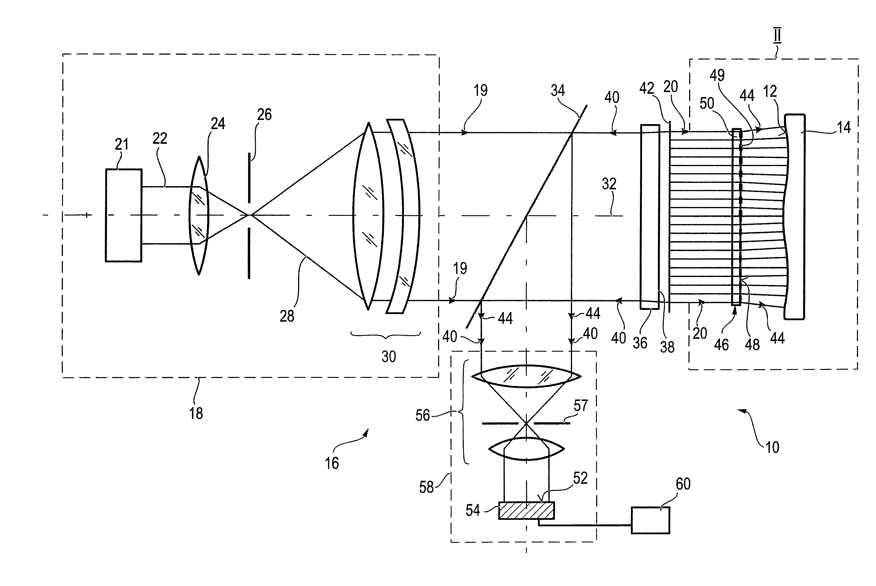
[0136]FIG. 8 shows the diffractive surface 264 of the diffractive calibration device 262 shown in FIG. 6, which can be used alternatively to the diffractive surface 264 shown in FIG. 7. The diffractive surface 264 according to FIG. 8 comprises a diffractive calibration structure 263 formed by first stripes 272 and second stripes 274 arranged in alternating sequence to form a super grating 284. For this purpose the stripes 272 and 274 are configured in a curved or bent shape and have variable width. The first stripes 272 each comprise a grating structure configured to form a first phase function. The super grating 284 formed by the stripes 272 and 274 is configured to form a second phase function.

[0137]The first phase function of the first stripes 272 is formed by a combination of a spherical phase sub-function and half of a given non-spherical phase sub-function coded with half of a tilt-carrier. The second phase function of the super grating 284 comprises half of the given non-sphe...

exemplary embodiment 1000

[0186]FIG. 24 shows a first exemplary embodiment 1000 of a projection objective for a projection exposure tool operating with EUV-radiation. The projection objective 1000 according to FIG. 24 includes six rotationally-asymmetric mirrors 1310, 1320, 1330, 1340, 1350, and 1360. An optical element of the above described type according to the invention is used as at least one of these mirrors, which is manufactured, e.g. using one of the calibration methods of the invention.

[0187]The projection objective 1000 images EUV-radiation from an object plane 1103 to an image plane 1102 along a reference axis 1105. Data for the projection objective 1000 is presented Table 1A and Table 1B below. Table 1A presents optical data, while Table 1B presents rotationally-asymmetric constants for each of the mirror surfaces. For the purposes of Table 1A and Table 1B, the mirror designations correlate as follows: mirror 1 (M1) corresponds to mirror 1310; mirror 2 (M2) corresponds to mirror 1320; mirror 3 (...


PUM

PropertyMeasurementUnit
Lengthaaaaaaaaaa
Diameteraaaaaaaaaa
Lengthaaaaaaaaaa

Abstract

Optical element having an optical surface, which optical surface is adapted to a non-spherical target shape, such that a long wave variation of the actual shape of the optical surface with respect to the target shape is limited to a maximum value of 0.2 nm, wherein the long wave variation includes only oscillations having a spatial wavelength equal to or larger than a minimum spatial wavelength of 10 mm.

Description

[0001]This application is a continuation of International Patent Application PCT / EP2008 / 005547, filed on Jul. 8, 2008, and claiming priority from International Patent Applications PCT / EP2007 / 006069 and PCT / EP2007 / 006639, filed on Jul. 9, 2007 and Jul. 26, 2007, respectively. The complete disclosures of these international patent applications are incorporated into this application by reference.FIELD OF AND BACKGROUND OF THE INVENTION[0002]The present invention relates to the technical field of manufacturing optical elements and testing of optical elements using a measuring apparatus like, for example, an interferometer. In particular, the present invention relates to a method of calibrating a measuring apparatus comprising a wave shaping device and an optical element manufactured for example using such a calibrated measuring apparatus.[0003]The optical element can for example be an optical lens or an optical mirror used in an optical system, such as a telescope used in astronomy or a...

Claims


Application Information

Patent Timeline
IPC IPC(8): G01B11/02
CPCG01B9/021G01B11/2441Y10T29/49771G01M11/0271G01M11/025G01B9/02039
Inventor HETZLER, JOCHENSCHILLKE, FRANKSCHULTE, STEFANFREIMANN, ROLFDOERBAND, BERND
Owner CARL ZEISS SMT GMBH
Why Eureka
Try Eureka