Adhesion method, and biochemical chip and optical component made by the same

a biochemical chip and optical component technology, applied in the direction of adhesion process with surface pretreatment, biomass after-treatment, synthetic resin layered products, etc., can solve the problems of difficult to achieve adhesion of an optical member such as a lens, difficult to achieve adhesion with no clearance, etc., to suppress thermal distortion generation, the degradation of optical properties due to discoloration, and the fine structure formed on the joining surface or optical properties.

Inactive Publication Date: 2010-07-15
EMPIRE TECH DEV LLC
View PDF2 Cites 4 Cited by
  • Summary
  • Abstract
  • Description
  • Claims
  • Application Information

AI Technical Summary

Benefits of technology

[0020]In the adhesion methods described in Claims 1 to 5, a first film compound and a second film compound covering a first joining surface and a second joining surface, respectively, are strongly bonded to the first joining surface and the second joining surface, respectively, via covalent bonds, and a first functional group and a second functional group are strongly bonded to each other via covalent bonds formed by coupling reactions with a coupling agent. Accordingly, the first joining surface can be strongly bonded to the second joining surface.
[0021]In addition, no adhesive is used, and thus adhesion can be achieved without impairing a fine structure formed on a joining surface or optical properties. Therefore, the methods can be suitably used in adhesion of a biochemical chip or an optical component.
[0022]In particular, in the adhesion method described in Claim 2, first, the coupling agent is brought into contact with the coating film of the first film compound formed on the first joining surface to form a bond by a coupling reaction between the first functional group and a first coupling reactive group, thereby forming a coating film of the coupling agent on the surface of the coating film of the first film compound, and the first joining surface further having the coating film of the coupling agent thereon is then brought into contact by pressure with the second joining surface having the coating film of the second film compound thereon to form a bond by a coupling reaction between the second functional group and a second coupling reactive group. Accordingly, excess coupling agent can be removed before adhesion. Therefore, elution of excess coupling agent after adhesion and degradation of optical properties due to discoloration can be suppressed.
[0023]In the adhesion method described in Claim 3, each of the first functional group and the second functional group is a functional group containing an epoxy group, and the coupling agent is a compound containing an imidazole group. Accordingly, strong bonds can be formed by heating at a relatively low temperature.
[0024]In the adhesion method described in Claim 4, each of the first surface bonding group and the second surface bonding group is an alkoxysilyl group. Accordingly, they can form a strong bond on a joining surface having an active hydrogen group such as a hydroxyl group via a covalent bond (siloxane bond).
[0025]In the adhesion method described in Claim 5, in step C, by heating the first member and the second member at the same temperature, generation of thermal distortion can be suppressed, and thus the dimensional accuracy of the first joining surface and the second joining surface in the adhesion can be improved.

Problems solved by technology

However, when a fine structure (for example, a hole or groove having a size of micrometers level) is provided on at least one of the joining surfaces, for example, as in the case of a member of a biochemical chip, it is very difficult to achieve adhesion with no clearance without filling the fine structure with a fluid adhesive.
In addition, by a known method using an adhesive, it is also very difficult to achieve adhesion of an optical member such as a lens without degrading optical properties thereof because the thickness of the adhesive or the like on a joining surface becomes uneven.

Method used


Image

  • Adhesion method, and biochemical chip and optical component made by the same
  • Adhesion method, and biochemical chip and optical component made by the same
  • Adhesion method, and biochemical chip and optical component made by the same

Examples


example 1

Production of Biochemical Chip

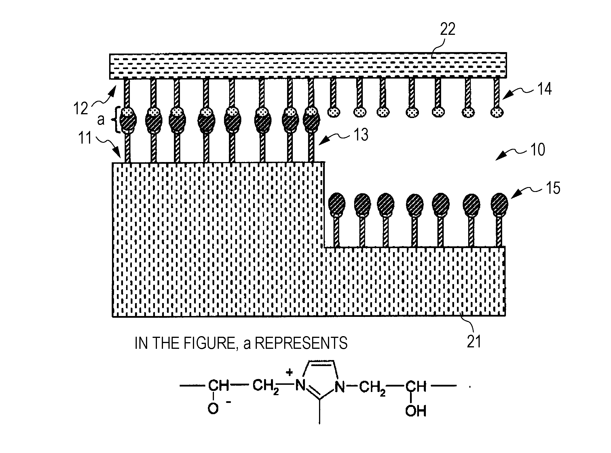
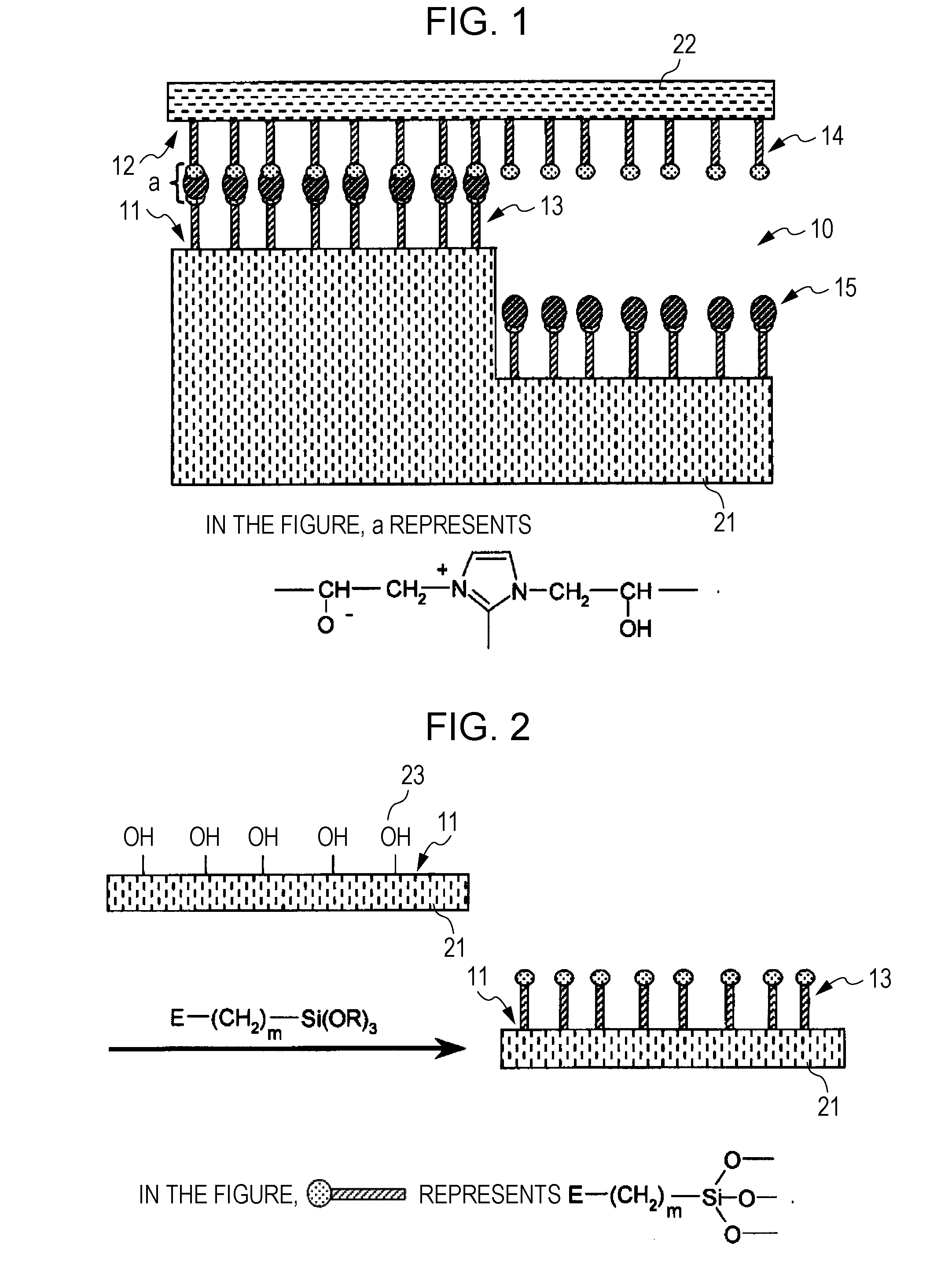
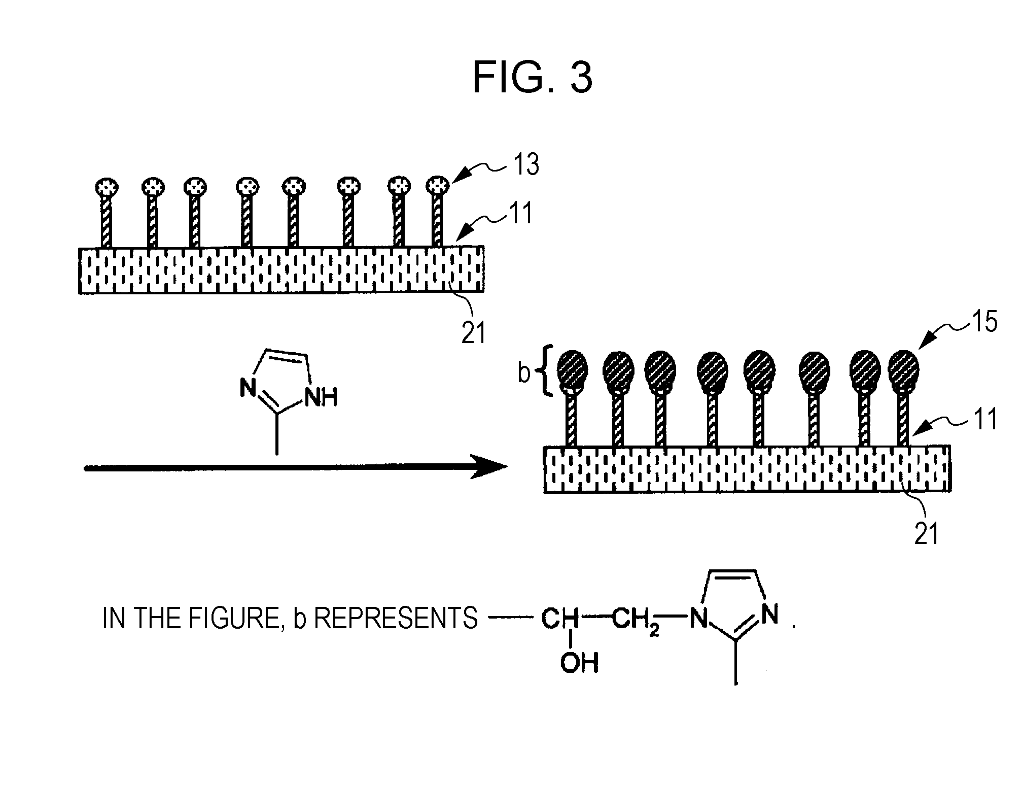
(1) Formation of Monomolecular Film of Film Compound Having Epoxy Group on Joining Surfaces of Biochemical Chip Substrates

[0105]A pair of glass biochemical chip substrates (a channel having a channel width in the range of 10 to 100 μm and a depth of about 50 μm was formed on one of the substrates by photolithography and wet etching) were prepared, sufficiently washed and then dried.

[0106]Subsequently, 0.99 parts by weight of 3-glycidyloxypropyltrimethoxysilane (Chem. 10, manufactured by Shin-Etsu Chemical Co., Ltd.) and 0.01 parts by weight of dibutyltin bisacetylacetonate (condensation catalyst) were weighed and then dissolved in 100 parts by weight of hexamethyldisiloxane to prepare a reaction mixture.

[0107]The reaction mixture thus prepared was applied onto a joining surface of each of the substrates and allowed to react in air (relative humidity: 45%) for about two hours. Subsequently, washing was performed with chloroform to remove excess alkoxysil...

example 2

Production of Cemented Lens

[0110]Adhesion of a cemented lens was achieved by the same method as in Example 1 using two lenses for a cemented lens. Regarding the resulting cemented lens, discoloration, distortion of the field of view, aberration, interference fringe formation, or the like was not observed.


PUM

PropertyMeasurementUnit
surface roughnessaaaaaaaaaa
pressureaaaaaaaaaa

Abstract

An adhesion method capable of strongly adhering two members without using an adhesive and without impairing a fine structure or optical properties of a joining surface, and a biochemical chip and optical component made by the same are provided.
The adhesion method includes step A of forming a coating film 13 of a first film compound having a first functional group on a first joining surface 11 of a first member 21, step B of forming a coating film 14 of a second film compound having a second functional group on a second joining surface 12 of a second member 22, and step C of bringing the first joining surface 11 into contact by pressure with the second joining surface 12 while bringing a coupling agent having at least one coupling reactive group that forms a bond by a coupling reaction with the first functional group and the second functional group into contact with the first and second functional groups to form bonds by the coupling reaction.

Description

TECHNICAL FIELD[0001]The present invention relates to an adhesion method and a biochemical chip and optical component made by the same. More specifically, the present invention relates to a method of achieving adhesion without using an adhesive by introducing a reactive functional group into a surface of each of joining surfaces by forming a coating film made of a film compound having the reactive functional group, and chemically bonding the joining surfaces via bonds formed between a coupling agent and the functional group, and a biochemical chip and optical component made by the same.BACKGROUND ART[0002]A technique in which two members are adhered to each other by applying an adhesive to one of or both of joining surfaces, pressure-bonding the joining surfaces to each other, and curing the adhesive is generally well known (see, for example, Patent Document 1). However, when a fine structure (for example, a hole or groove having a size of micrometers level) is provided on at least ...

Claims


Application Information

Patent Timeline
Patent Type & Authority Applications(United States)
IPC IPC(8): C09J5/02C09J163/00C09J5/04C09J201/02C12M1/00B01L3/00G02B1/00
CPCC09J5/04B32B27/38B01L3/00C09J2463/00Y10T428/31536Y10T428/31515
Inventor OGAWA, KAZUFUMI
Owner EMPIRE TECH DEV LLC
Why Eureka
Try Eureka