Methods of deploying and retrieving an embolic diversion device

a technology of embolic diversion device and embolic debris, which is applied in the field of systems and methods for deflection of embolic debris, can solve the problems of both carotid arteries at risk of emboli, stroke or even death, and carotid emboli, so as to reduce the risk of emboli entering and reduce the risk of emboli

Inactive Publication Date: 2010-07-15
EDWARDS LIFESCIENCES AG
View PDF102 Cites 144 Cited by
  • Summary
  • Abstract
  • Description
  • Claims
  • Application Information

AI Technical Summary

Benefits of technology

[0029]In another embodiment, disclosed herein is a method of reducing the risk of emboli entering the cerebral circulation as a consequence of an index procedure in the heart. The method includes the steps of introducing an elongate, flexible shaft into the vasculature at a point other than a femoral artery, the shaft carrying a deflector thereon; positioning the deflector in the aorta such that it spans the ostium of at least the brachiocephalic and left common carotid arteries; introducing an index procedure catheter into the femoral artery; advancing the index procedure catheter across the thoracic aorta and to a treatment site in the heart; conducting the index procedure in the heart; removing the index procedure catheter from the patient; and removing the deflector from the patient. In some embodiments, the index procedure could be a transcatheter aortic valve implantation, a balloon aortic or mitral valvuloplasty, a mitral or aortic valve replacement, a heart valve repair, or a coronary angioplasty. In some embodiments, the deflector is introduced into the vasculature via, for example, the ulnar, radial, brachial, axillary, subclavian, or brachiocephalic arteries, or into the aorta. In some embodiments, the def

Problems solved by technology

One potential problem which is common to all these endovascular manipulations is that plaque found in the diseased vessels and valves can be dislodged and result in embolization.
Similarly, a potential complication resulting from endovascular treatment of cardiac valves or the thoracic aorta is that the dislodged debris can embolize into the carotid vessels resulting in catastrophic consequences such as stroke or even death.
Any procedure involving the passage of catheters across the aortic arch carries this risk of causing carotid emboli.
These procedures simultaneously place both carotid arteries at risk for emboli.
The chance of causing a stroke by the placement of a protective device into both carotid arteries makes the risk of using these devices prohibitive.
Limitations of this device include its applicability only to open heart surgery, excluding its use in the vast array of endovascular procedures requiring protection.
Adoption of the device has been hampered by ease of use, as operators often find it cumbersome.
The device could not be adapted to endovascular procedures as

Method used


Image

  • Methods of deploying and retrieving an embolic diversion device
  • Methods of deploying and retrieving an embolic diversion device
  • Methods of deploying and retrieving an embolic diversion device

Examples


Embodiment Construction

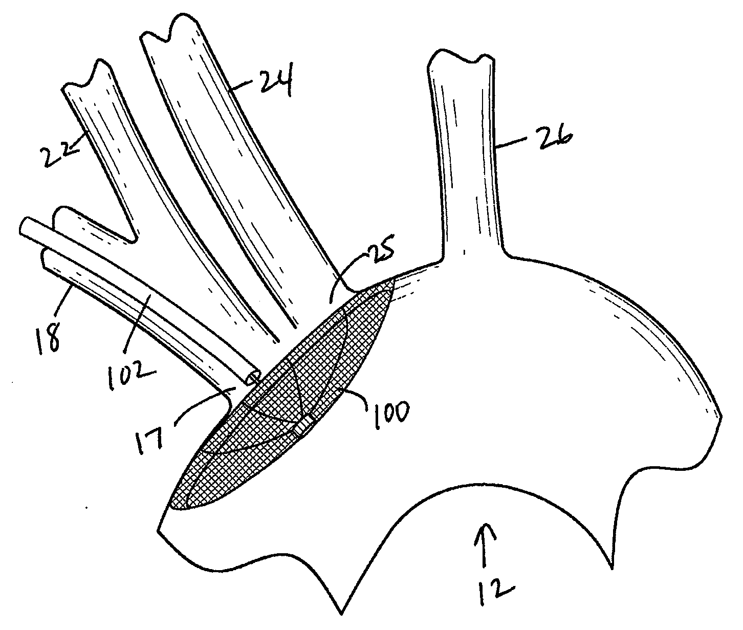
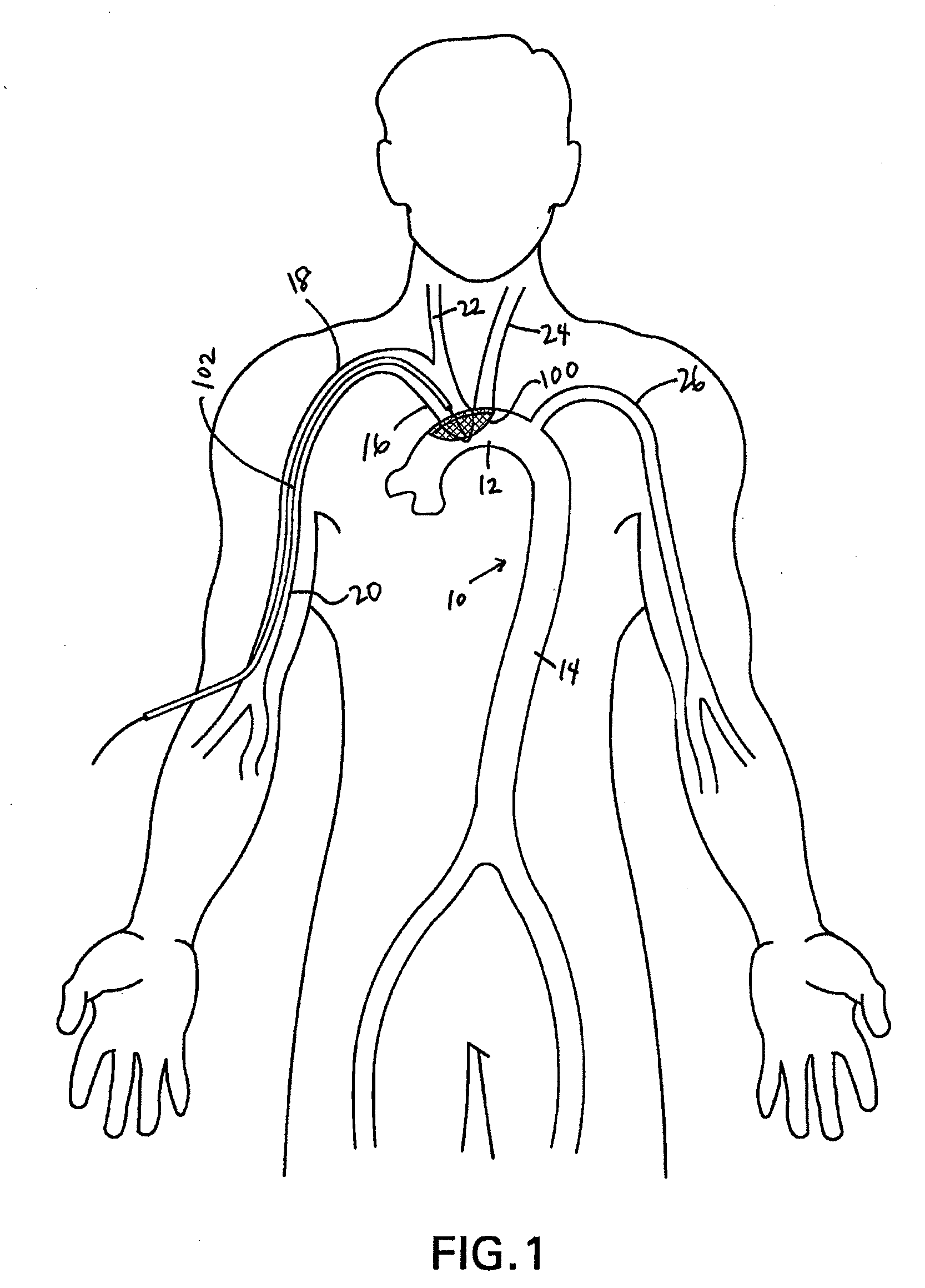
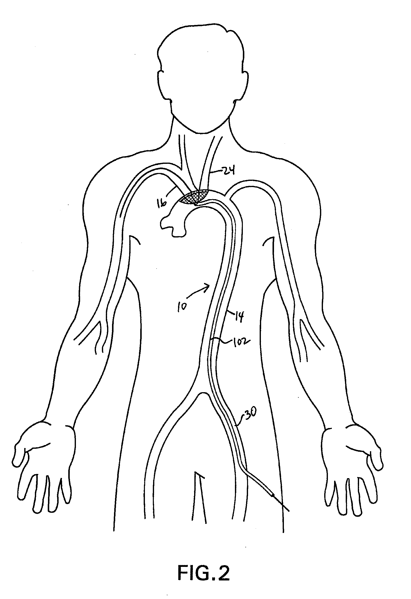
[0050]Disclosed herein are embolic protection systems that includes a deflector, along with associated deployment and removal systems, that can advantageously prevent emboli above a predetermined threshold size from entering the cerebral vasculature that may be dislodged, such as during an index procedure, such as an operative procedure. As such, potentially life-threatening transient ischemic attacks or embolic strokes can be prevented. Conventional embolic filters are primarily configured to capture, retain and retrieve embolic material. In contrast, deflectors as disclosed herein are configured to deflect or otherwise divert embolic material to a location downstream (relative to the direction of blood flow in the vessel in which the deflector is deployed) of the deployed location of the deflector to a less critical region of the body rather than the brain and other tissues perfused by the carotid and vertebral arteries. Once downstream, the emboli can be acted upon by physiologic...


PUM


Abstract

There is disclosed a porous emboli deflector for preventing cerebral emboli while maintaining cerebral blood flow during an endovascular or open surgical procedure. The device prevents the entrance of emboli of a size able to cause stroke (such as greater than 100 microns) from entering either the right or left common carotid arteries, and/or the right or left vertebral arteries by deflecting emboli downstream of these vessels. The device can be placed prior to any manipulation of the heart or aorta allowing maximal protection of the brain during the index procedure. The deflector has a low profile within the aorta which allows sheaths, catheters, or wires used in the index procedure to pass. Also disclosed are methods for insertion and removal of the deflector.

Description

PRIORITY CLAIM[0001]This application claims priority under 35 U.S.C. §119(e) as a nonprovisional of U.S. Provisional App. No. 61 / 143,426 filed on Jan. 9, 2009, and also claims priority under 35 U.S.C. §120 as a continuation-in-part application of U.S. patent application Ser. No. 12 / 440,839 filed on Mar. 11, 2009, currently pending, which is a 35 U.S.C. §371 national stage application of PCT Application No. PCT / US2007 / 078170 filed on Sep. 11, 2007, which is a continuation-in-part application of U.S. patent application Ser. No. 11 / 518,865, filed on Sep. 11, 2006, currently pending. This application also claims priority as a continuation-in part application of PCT Application No. PCT / US2010 / 020530 filed on Jan. 8, 2010, which claims priority to the aforementioned U.S. Provisional App. No. 61 / 143,426 filed on Jan. 9, 2009. All of the aforementioned priority applications are hereby incorporated by reference in their entireties.BACKGROUND OF THE INVENTION[0002]1. Field of the Invention[00...

Claims


Application Information

Patent Timeline
IPC IPC(8): A61M29/00
CPCA61F2/013A61F2002/011A61F2002/016A61F2002/018A61F2230/0006A61F2230/0095A61F2230/0019A61F2230/0021A61F2230/005A61F2230/008A61F2230/0093A61F2230/0008A61F2/011
Inventor CARPENTER, JUDITH T.CARPENTER, JEFFREY P.REZAC, DAVID A.CERIER, JEFFREY C.FORTIER, RICHARD C.ROBINSON, TIMOTHY W.
Owner EDWARDS LIFESCIENCES AG
Why Eureka
Try Eureka