Sensor-enabled geosynthetic material and method of making and using the same

a technology of geosynthetic materials and sensors, applied in the direction of instruments, non-metal conductors, conductors, etc., can solve the problems of imposing overly conservative design procedures and reduction factors on the strength, comparatively little attention, and costly consequences on the installation of instruments

Inactive Publication Date: 2010-07-22
THE BOARD OF RGT UNIV OF OKLAHOMA
View PDF23 Cites 18 Cited by
  • Summary
  • Abstract
  • Description
  • Claims
  • Application Information

AI Technical Summary

Problems solved by technology

Unfortunately, a vital aspect of sustainable development; namely, their instrumentation and health monitoring has received comparatively little attention with costly consequences.
A significant predicament in performance monitoring of geosynthetic structures has been due to the fact that installation of instruments (e.g. strain gauges) are typically tedious and costly with rather unpredictable outcome.
As a result, overly conservative design procedures and reduction factors are typically imposed on the strength of the geosynthetic material to address concerns related to their durability and creep.
This renders the cost of these structures in many instances much greater than necessary, and counters their intrinsic cost-effectiveness.
Current technology merely involves leak detection systems which could only detect the problems in more advanced stages.
In addition, the existing technology currently employed to measure strains in geosynthetics requires complex and expensive data acquisition systems.
However, these calibration factors are not truly applicable to a geosynthetic layer embedded in soil due to at least three important reasons: 1) different in-soil mechanical properties (e.g. tensile modulus) of geosynthetics compared to their in-isolation values due to confining pressure and interlocking effects, 2) complications such as soil arching due to the mechanical interference and interaction of strain gauges and their bonding assembly (e.g. adhesive and protective sleeve) with the local soil, 3) unknown local stiffening effect of the bonding assembly.
These factors can introduce significant errors in measured strains in geosynthetics in field applications.
Applying in-isolation calibration factors to in-soil readout data could lead to significant underestimation of reinforcement strain and axial load with potential consequences with respect to stability and performance.
In addition, geosynthetic strain is not routinely monitored in the field due to the added costs and level of care and skills required for proper installation of the instruments.
Other impediments include lack of reliable strain gauging techniques and proper training of contractors, durability and reliability of instruments and requirements for time-consuming installation and protection measures.
For these reasons, geosynthetic instrumentation in the field has been primarily limited to research and demonstration projects with a comparatively insignificant footprint in their mainstream construction considering the vast number of geosynthetic-related structures constructed in the U.S. In those occasions where field structures have been instrumented, the extent of instrumentation related to the geosynthetic strain data has been fairly limited.
As a result, important information on the extent and distribution of strains and stresses in these structures is not typically available.
However, the limited in-soil penetration range of these techniques renders them impractical for field-scale structures.
However, these techniques do not incorporate the sensing capabilities within the geosynthetic materials, and the added manufacturing and construction costs related to the fiber optic material and their installation need further analysis.

Method used


Image

  • Sensor-enabled geosynthetic material and method of making and using the same
  • Sensor-enabled geosynthetic material and method of making and using the same
  • Sensor-enabled geosynthetic material and method of making and using the same

Examples


Embodiment Construction

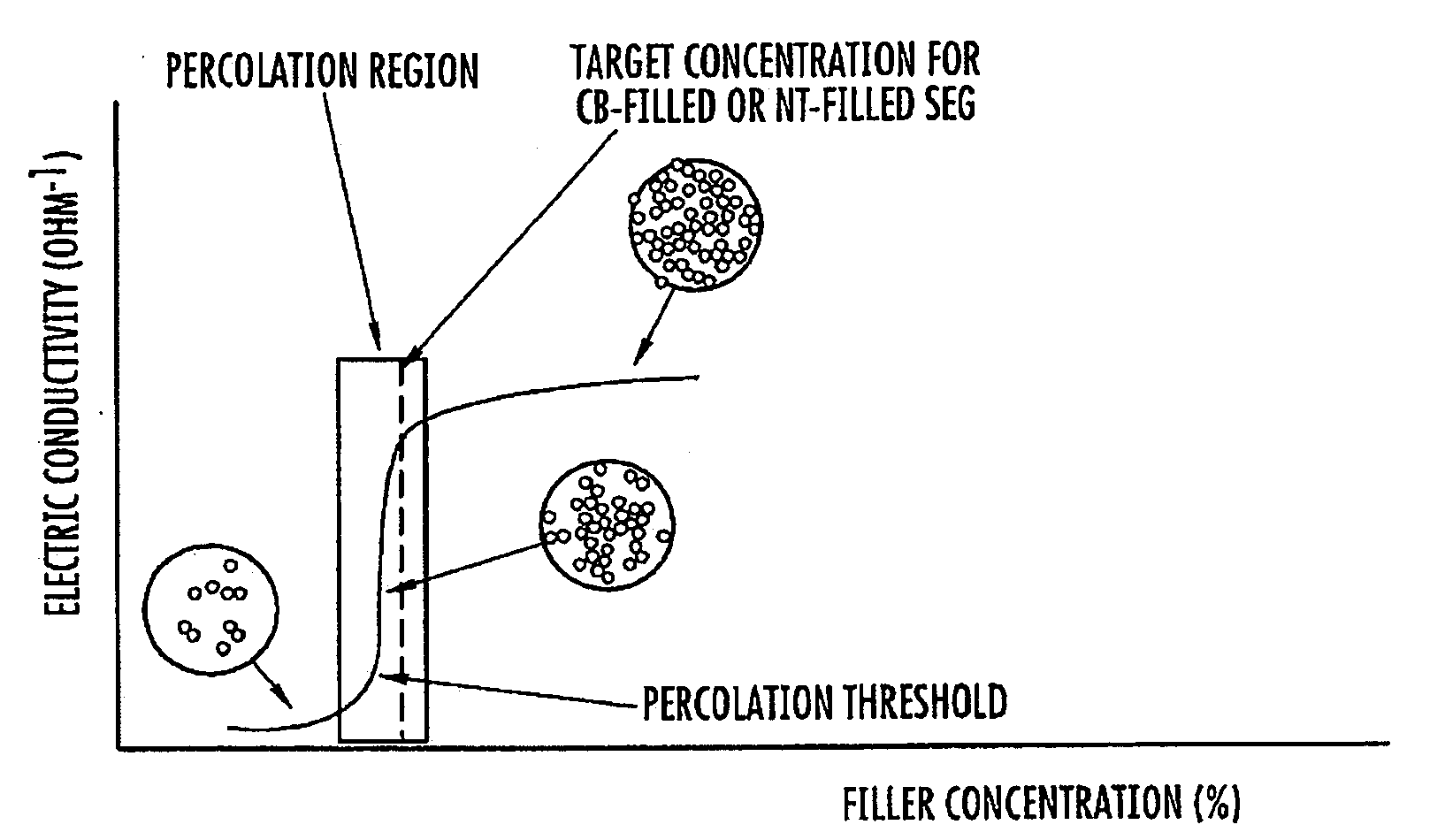
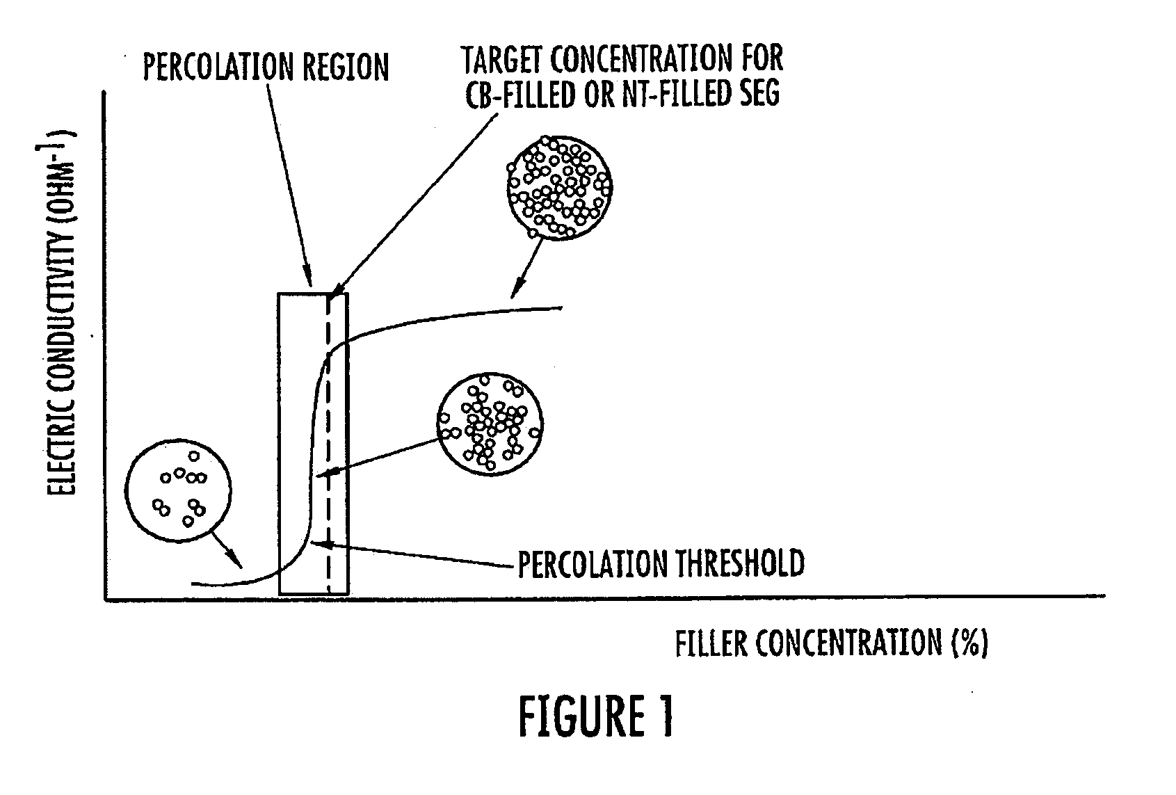
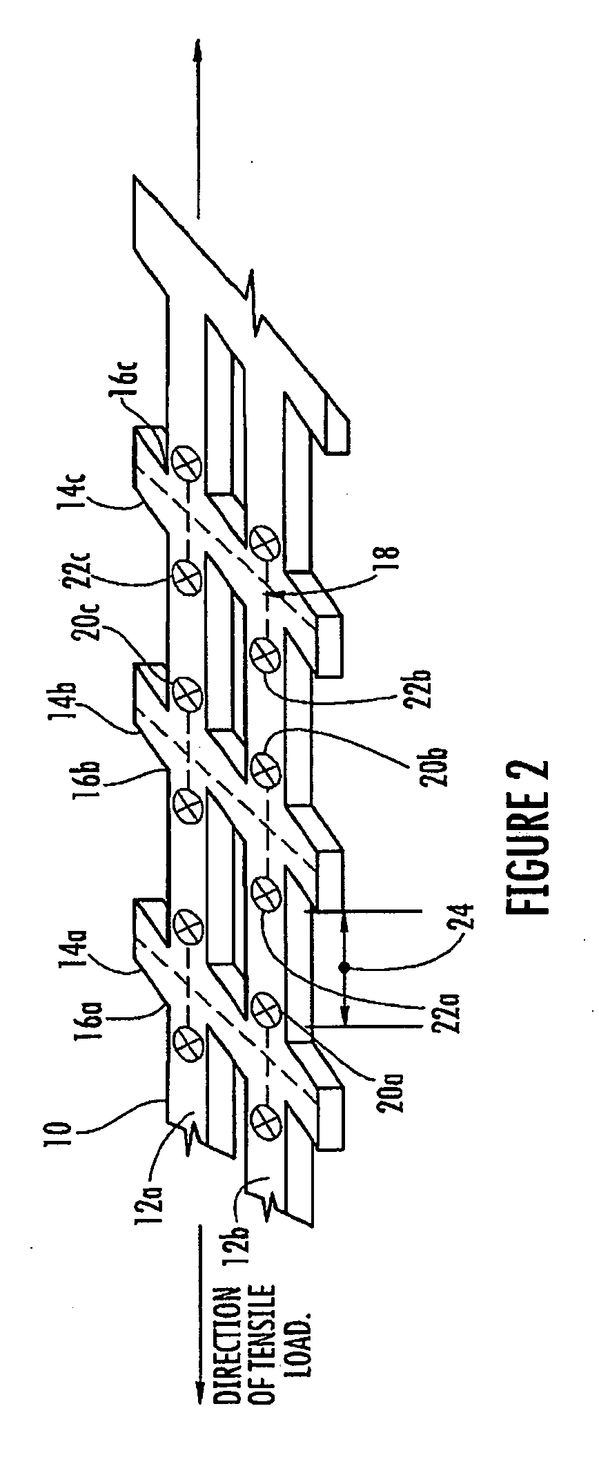
[0036]The present invention relates to a sensor-enabled geosynthetic (SEG) material used for constructing geosynthetic structures, such as geogrids and geomembranes, which are used in reinforcement and containment applications. The sensor-enabled geosynthetic material is embedded with sensing capabilities in order to measure the mechanical strains subjected on the geosynthetic structures at any location of the geosynthetic structures. As the mechanical strains on a geosynthetic structure change, the conductivity of the sensor-enabled geosynthetic material is affected.

[0037]Generally, the sensor-enabled geosynthetic material includes a polymeric material (or geosynthetic material) and an electrically conductive filler. The polymeric materials used in geosynthetic structures are typically electrically insulating materials. An electrically conductive filler is added to the polymeric material in sufficient amounts to transform the polymeric material from an insulating material into a co...


PUM

PropertyMeasurementUnit
compressive stressaaaaaaaaaa
aperture sizeaaaaaaaaaa

Abstract

The present invention is directed to a sensor-enabled geosynthetic material for use in geosynthetic structures, a method of making the sensor-enabled geosynthetic material, and a method of measuring geometric strains of a geosynthetic product made from the sensor-enabled geosynthetic material. The sensor-enabled geosynthetic material includes a polymeric material and an electrically conductive filler. The polymeric material and an electrically conductive filler are combined to provide a sensor-enabled geosynthetic material. The sensor-enabled geosynthetic material having a predetermined concentration of the electrically conductive filler so as to provide the sensor-enabled geosynthetic material with an electrical conductivity and a strain sensitivity within the percolation region or slightly above it.

Description

STATEMENT REGARDING FEDERALLY SPONSORED RESEARCH OR DEVELOPMENT[0001]Not Applicable.CROSS-REFERENCE TO RELATED APPLICATIONS[0002]Not Applicable.BACKGROUND OF THE INVENTION[0003]1. Field of the Invention[0004]The present invention relates to a sensor-enabled geosynthetic material used to construct geosynthetic structures (i.e. geotechnical structures involving geosynthetics) and a method of making the sensor-enabled geosynthetic material. Additionally, the mechanical strains of the sensor-enabled geosynthetic material can be measured or monitored without the need for conventional instrumentation.[0005]2. Description of the Related Art[0006]Geosynthetics are polymer-based products specifically manufactured to serve a wide range of applications in civil and environmental engineering including soil stabilization and reinforcement, separation and filtration, drainage and containment. The emergence and development of geosynthetic technology has had a significant impact on the capabilities...

Claims


Application Information

Patent Timeline
Patent Type & Authority Applications(United States)
IPC IPC(8): G01N3/00H01B1/20H01B1/24H01B1/22
CPCG01L1/20G01L1/205E02D17/202G01M5/0083G01N2203/0244G01N2203/0617G01N2203/0664G01B7/18
Inventor HATAMI, KIANOOSHGRADY, BRIAN
Owner THE BOARD OF RGT UNIV OF OKLAHOMA
Why Eureka
Try Eureka