Valve timing control device

Active Publication Date: 2010-07-22
DENSO CORP
View PDF6 Cites 18 Cited by
  • Summary
  • Abstract
  • Description
  • Claims
  • Application Information

AI Technical Summary

Benefits of technology

[0062]According to a different aspect, the power supply control means stops the power supply to the electric motor when a set time elapses after the power supply amount to the electric motor starts to increase. According to such a construction, when the set time elapses after the power supply amount to the electric motor starts to increase, the motor torque is to balance with the magnetic retaining torque and the cam torque. Since it is possible to automatically stop the power supply under such a condition, the processing required for such a balance can be simplified.
[0063]According to a different aspect, the control unit includes the motor determining means for determining the operational state of the motor shaft, and the power supply control means, when the motor determining means makes the angle change determination that the rotational angle of the motor shaft changes after the power supply to the electric motor stops, repeats the power supply control that the stop of the power supply is replaced by actions such as by first reducing the power supply amount to the electric motor. According to such a construction, when the motor shaft in which the torque balance is disrupted is rotated to make the angle change determination in the stop state of the power supply, the power supply amount is increased from the power supply stop state to be replaced by first reducing the power supply amount, thereby making it possible to first better establish the balance of the motor torque with the magnetic retaining torque and the cam torque. Therefore, by the elimination of the m

Problems solved by technology

Therefore, such a device leads to increased complexity and size of the device structure.
The torque balance in the brake shaft is disrupted depending upon the positive or the negative direction of the cam torque or the magnitude of the cam torque, possibly creating a large shift of the engine phase from the start phase.
According to various studies conducted in connection with the present application, since the magnetic retaining torque alternates between a positive and a negative torque direction in response to the rotation of the motor shaft, it becomes difficult to

Method used


Image

  • Valve timing control device
  • Valve timing control device
  • Valve timing control device

Examples


Example

First Embodiment

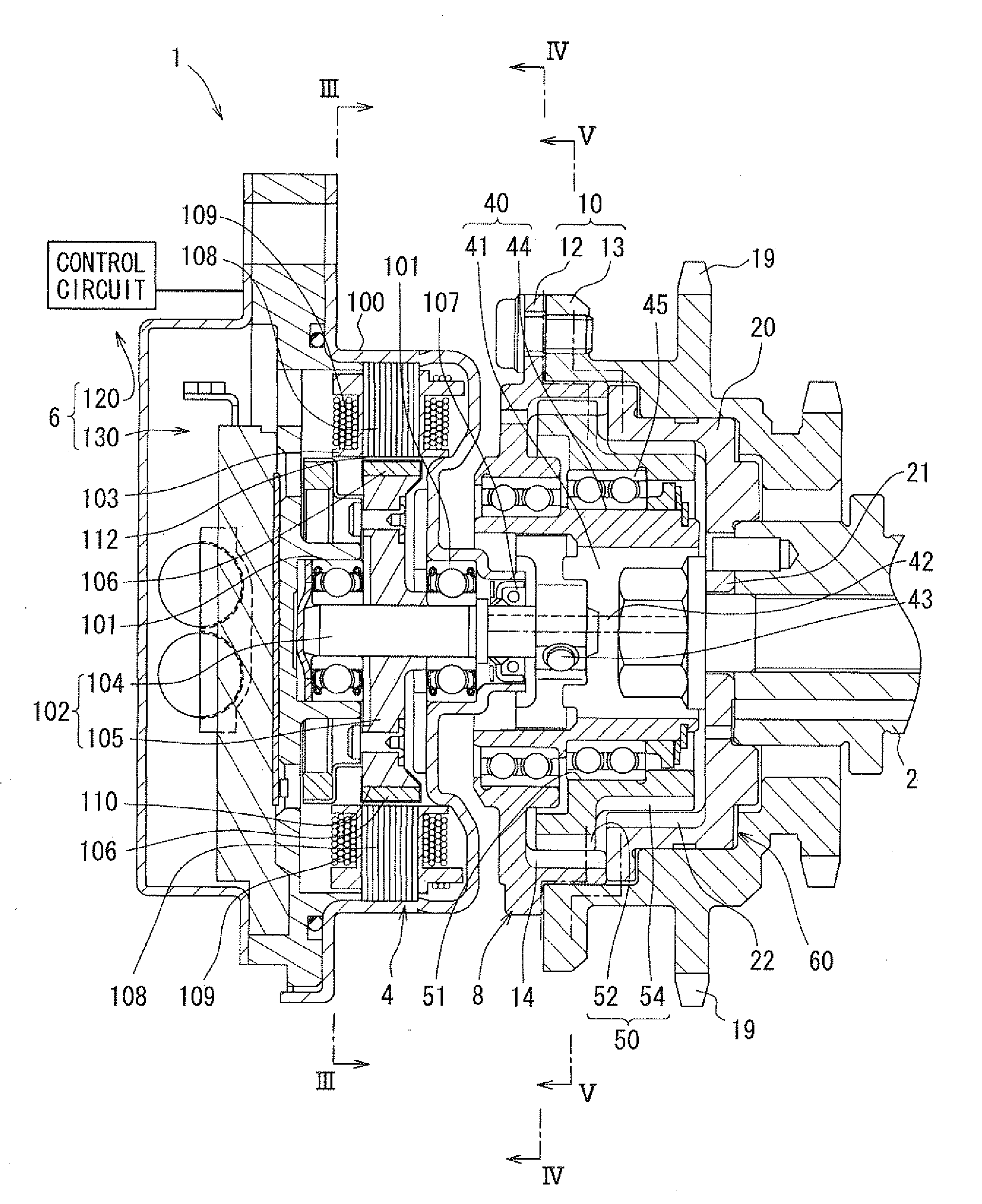
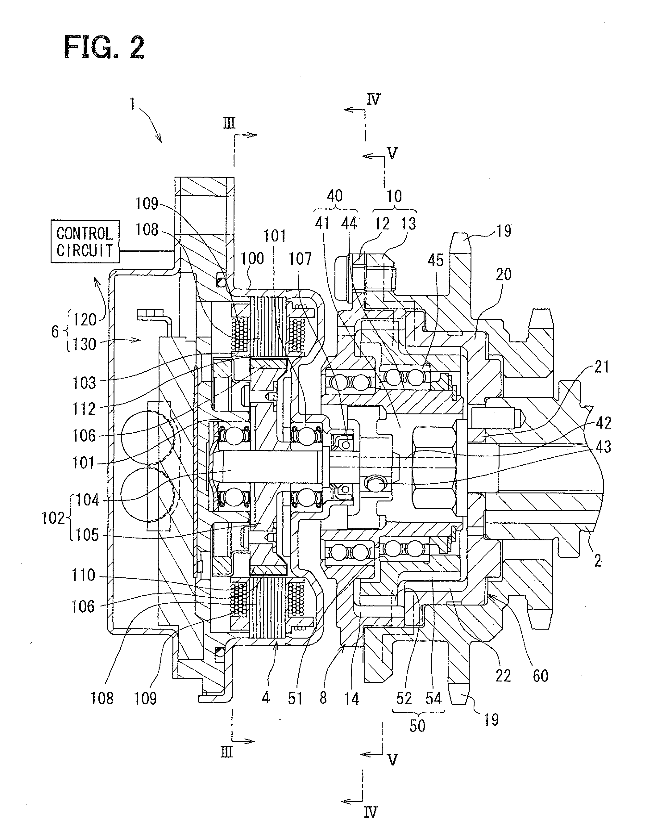
[0109]FIG. 2 shows a valve timing control device 1 according to a first embodiment. The valve timing control device 1 is provided in a transmission system mounted in a vehicle for transmitting engine torque from a crank shaft (not shown) to a cam shaft 2 of an internal combustion engine mounted in a vehicle.

[0110]Hereinafter, a basic construction of the valve timing control device 1 will be explained. The valve timing control device 1 can be configured to combine an electric motor 4, a power supply control system 6 and a phase control mechanism 8, and controls an engine phase between the crank shaft and the cam shaft 2 for determining valve timing. In the present embodiment, the cam shaft 2 opens / closes an intake valve (not shown) of the internal combustion engine, and the valve timing control device 1 controls the valve timing of the intake valve.

[0111]As shown in FIG. 2 and FIG. 3, the electric motor 4 can be a brushless motor provided with a housing 100, bearings ...

Example

Second Embodiment

[0161]A second embodiment is, as shown in HG. 15, a modification of a first embodiment. In the torque eliminating processing with the correctness / incorrectness determination by S105 in a second embodiment, after correctness / incorrectness of the determination direction Dca0 is determined according to a first embodiment, a brake torque is applied to the motor shaft 102 to gradually eliminate the motor torque Tm.

[0162]More specifically, after the control circuit 120 makes the correctness / incorrectness determination of the determination direction Dca0 to balance the torques Tm, Tca and Th, the control circuit 120 first sets the target rotational number St, the target rotational direction Dt and the target drive system Ft as the OR control values and outputs the results to the power supply block 134 of the drive circuit 130. The target rotational number St is set as a predetermined intermediate value between an initial value at a correctness / incorrectness determination t...

Example

Third Embodiment

[0167]As shown in FIG. 16, a third embodiment is a modification of a first embodiment. In the control processing at the stop time in a third embodiment, S104 is not executed after executing S101 to S103, and the torque eliminating processing with the direction determination is executed as S204, different from S105 of a first embodiment.

[0168]More specifically, at S204, except for setting the target rotational direction Dt to a set direction Ds, which is determined in advance, the motor torque Tm corresponding to the initial value of the target rotational number St is first generated according to the correctness / incorrectness determination of the determination direction Dca0 in a first embodiment.

[0169]Thereby, when the motor torque Tm is generated in the set direction Ds to correctly oppose the cam torque Tca, the motor torque Tm balances with the torques Tca and Th without rotation of the motor shaft 102 or when the motor shaft 102 slightly rotates in the reverse di...


PUM


Abstract

A valve timing control device is provided with an electric motor (4) generating a magnetic retaining torque (Th) and a motor torque (Tm) in a motor shaft (102) based on a power supply. A power supply control system (6) controls the motor torque (Tm) by controlling the power supply supplied to the electric motor (4). A phase control mechanism (8) transmits a cam torque (Tca) that can alternate between a positive and a negative direction in response to rotation of a cam shaft, to the motor shaft (102) and controls a relative phase between the crank shaft and the cam shaft in accordance with a torque balance in the motor shaft (102). The power supply control system (6) eliminates the motor torque (Tm) that is balanced with the magnetic retaining torque (Th) and the cam torque (Tca) after a stop of the internal combustion engine (S105).

Description

CROSS REFERENCE TO RELATED APPLICATION[0001]The present application is based on and incorporates herein by reference Japanese Patent Application No. 2007-148607 filed on Jun. 4, 2007 and Japanese Patent Application No. 2008-130009 filed on of May 16, 2008.TECHNICAL FIELD[0002]The present application is related to a valve timing control device in an internal combustion engine for controlling valve timing of at least one of an intake valve and an exhaust valve opened / closed by a cam shaft through torque transmission from a crank shaft.BACKGROUND ART[0003]A conventional valve timing control device controls a relative phase between a crank shaft and a cam shaft, which is hereinafter referred to as an “engine phase,” to determine a valve timing by applying torque generated by an electric motor or an electromagnetic actuator such as an electromagnetic brake device to a phase control mechanism. JP2005-146993A describes a valve timing control device that ensures start performance of an inte...

Claims


Application Information

Patent Timeline
IPC IPC(8): F01L1/34F02D41/00
CPCF01L1/022F01L1/352F01L2800/00Y02T10/18F01L2800/03F01L2820/032F02D13/0219F01L2800/01F01L1/34409F01L2201/00F02D2013/0292Y02T10/12F01L1/34F01L13/00F02D13/02
Inventor UEHAMA, MOTOKIMORII, YASUSHI
Owner DENSO CORP
Why Eureka
Try Eureka