Apparatus & method for passive purging of micro-perforated aerodynamic surfaces

a technology of aerodynamic surfaces and filters, applied in the direction of airflow influencers, fuselages, transportation and packaging, etc., can solve the problems of reducing the effectiveness wide-spread implementation of laminar flow control systems, contamination or blockage of pores, etc., to reduce the potential for blockage of pores formed in porous skin

Active Publication Date: 2010-07-22
THE BOEING CO
View PDF30 Cites 32 Cited by
  • Summary
  • Abstract
  • Description
  • Claims
  • Application Information

AI Technical Summary

Benefits of technology

[0013]These and other needs associated with purging systems for laminar flow control systems are specifically addressed and alleviated by the embodiments disclosed herein comprising a passive purging system for clearing pores in a porous skin. Advantageously, the purging system ...

Problems solved by technology

One of the challenges preventing widespread implementation of laminar flow control systems of the suctioning type is contamination or blockage of pores which can occur under certain conditions.
Such contamination may include atmospheric contamination and/or manmade contamination which can reduce the effectiveness of laminar flow control systems.
The frozen moisture blocks the pores and reduces the effectiveness of the suctioning system in maintaining laminar flow over the aircraft during cruise.
Manmade contamination such as de-icing fluids applied during ground operations may also reduce the effectiveness of the laminar flow control system by clogging the pores with de-icing fluid.
The accumulation of frost on an aircraft may also reduce the effectiveness of a suctioning system by blocking the pores.
Although frost accumulations on exterior skin surfaces of the porous skin may eventually sublimate away, moisture or liquid on the interior skin surfaces of the porous skin may become trapped in the pores and will remain as a result of the relat...

Method used


Image

  • Apparatus & method for passive purging of micro-perforated aerodynamic surfaces
  • Apparatus & method for passive purging of micro-perforated aerodynamic surfaces
  • Apparatus & method for passive purging of micro-perforated aerodynamic surfaces

Examples


Embodiment Construction

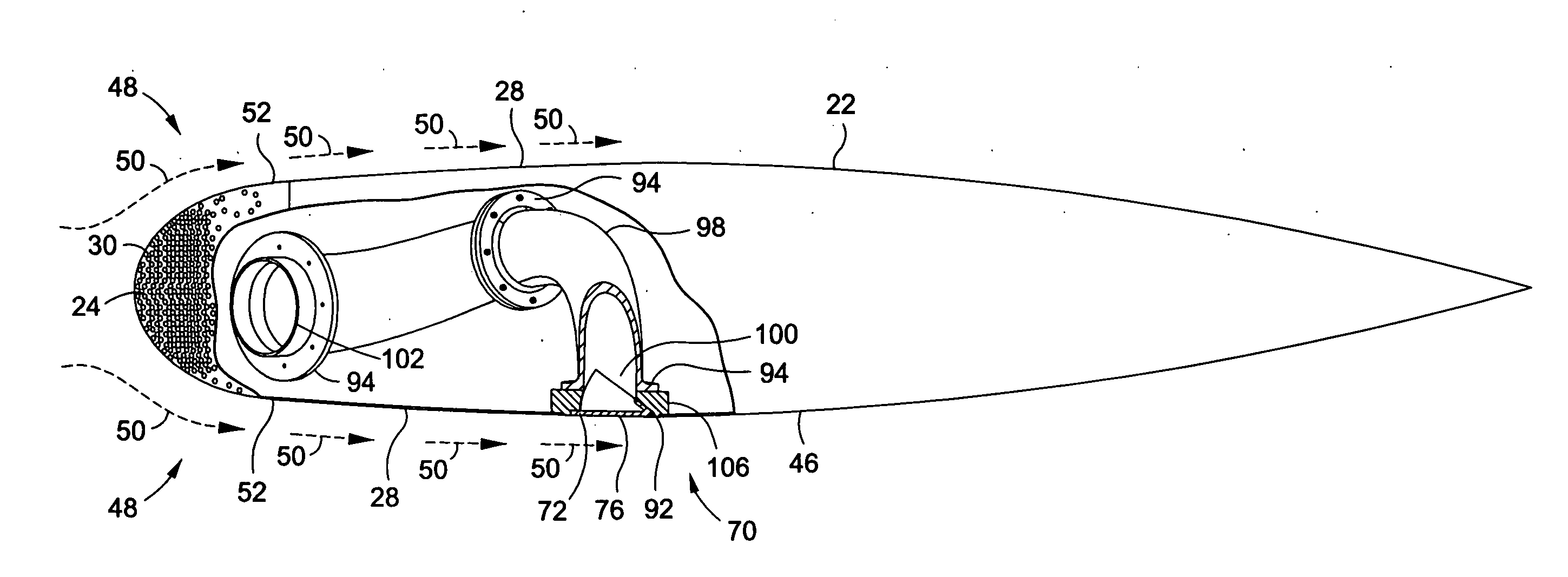
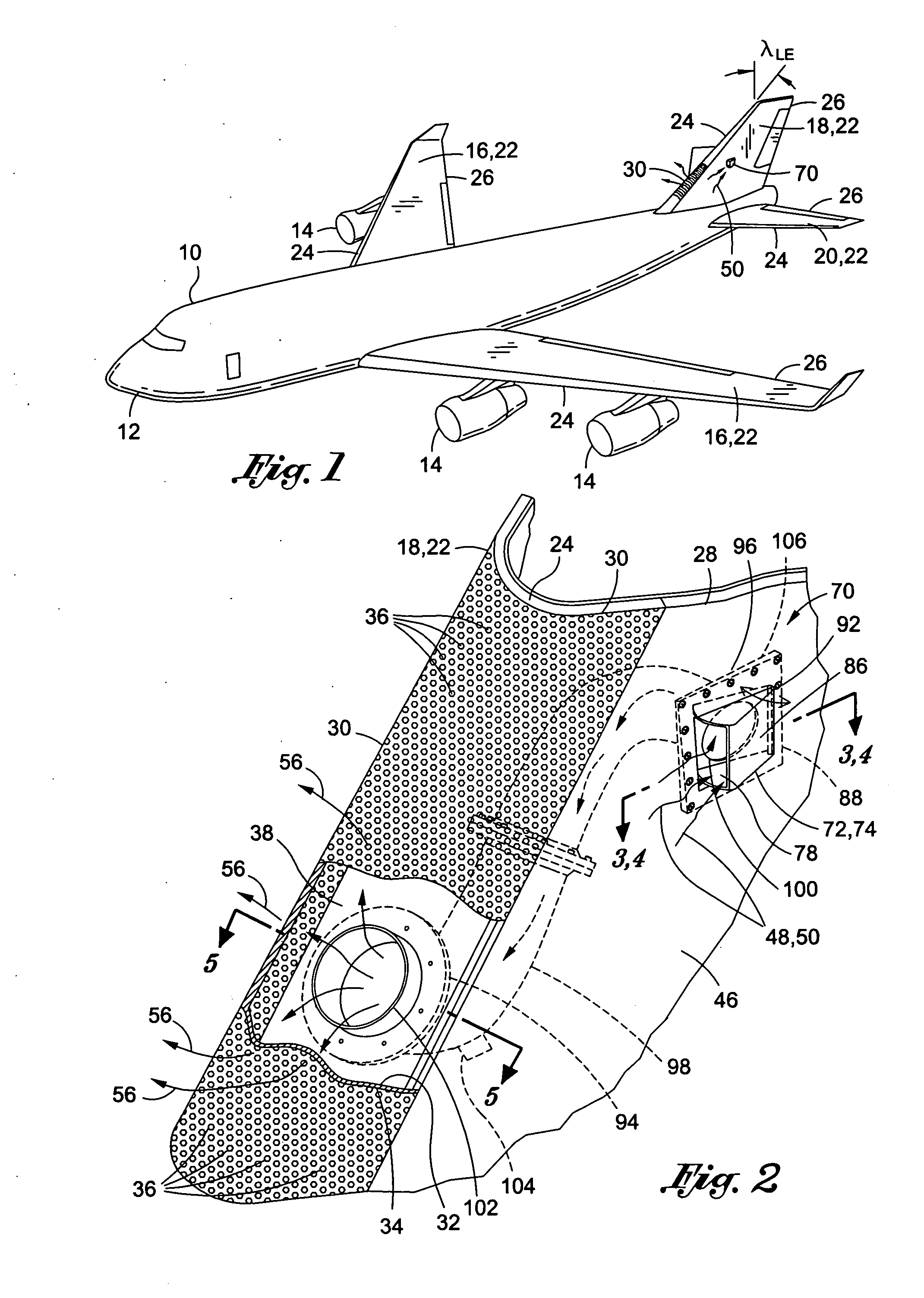
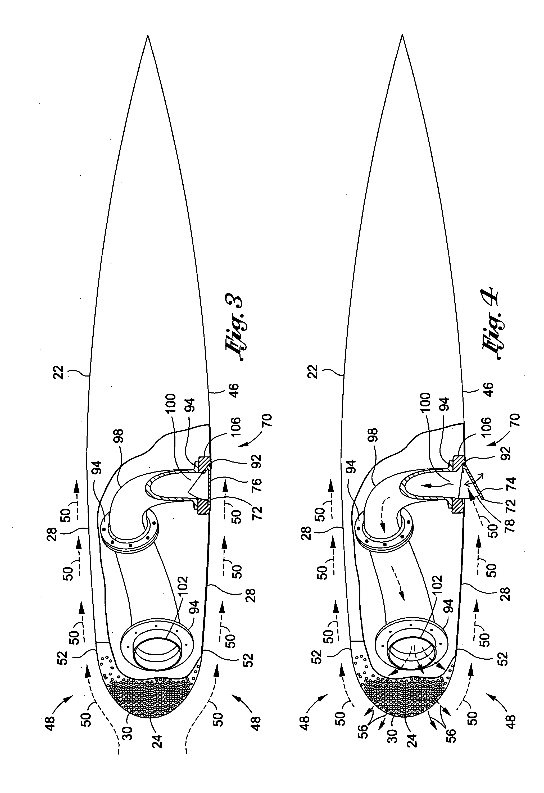
[0040]Referring now to the drawings wherein the showings are for purposes of illustrating preferred and various embodiments of the disclosure only and not for purposes of limiting the same, shown in the figures is a purging system 70 and method for passively purging of pores 36 formed in a porous skin 30 which may be a part of a laminar flow control system. The passive purging system 70 comprises an air scoop 72 which is disposable into a high pressure external flow 50 of an external atmosphere 48. The external flow 50 may be ducted to a suction cavity 38 which also may form a part of the laminar flow control system. The ducted flow is discharged through the pores 36 in order to reduce the potential for blockage of the pores 36 such as from moisture, condensation, rain, snow, de-icing fluids, debris, insect residue and other contaminants.

[0041]Although illustrated as being installed on an aircraft 10 in FIG. 1, it should be noted that the purging system 70 as disclosed herein may be...


PUM


Abstract

A purging system for a laminar flow control system comprises an air scoop and a diffuser fluidly connected thereto. The air scoop is disposable into an external flow of an external atmosphere. The diffuser is configured to fluidly connect the air scoop to a suction cavity of the laminar flow control system wherein the suction cavity may be disposed adjacent a porous skin of an airfoil such as adjacent a leading edge of the airfoil. The laminar flow control system may be configured to suction boundary layer flow passing over the porous skin by drawing a portion of the boundary layer flow through a plurality of pores formed in the porous skin. The diffuser ducts high pressure flow captured by the air scoop to the suction cavity for discharge through the pores to reduce the potential of blockage thereof.

Description

CROSS-REFERENCE TO RELATED APPLICATIONS[0001]This application is related to co-filed Application Serial No. (unknown) entitled DOOR ASSEMBLY FOR LAMINAR FLOW CONTROL SYSTEM filed on Jan. 19, 2009. This application is also related to application Ser. No. 11 / 763,569 entitled PASSIVE REMOVAL OF SUCTION AIR FOR LAMINAR FLOW CONTROL AND ASSOCIATED SYSTEMS AND METHODS filed on Jun. 15, 2007. The entire contents of the above-mentioned applications are expressly incorporated herein by referenceSTATEMENT RE: FEDERALLY SPONSORED RESEARCH / DEVELOPMENT[0002](Not Applicable)FIELD[0003]The present disclosure relates generally to laminar flow control systems for aerodynamic surfaces and, more particularly, to a system and method of purging a porous skin of an airfoil by discharging pressurized air through pores formed in the porous skin.BACKGROUND[0004]It is generally known that maintaining laminar flow of air passing over an airfoil can improve the aerodynamics and performance of an aircraft. For ...

Claims


Application Information

Patent Timeline
IPC IPC(8): B64C21/06
CPCB64C21/08B64C2230/22Y02T50/166B64F5/0018B64F5/30Y02T50/10B64C21/025
Inventor POWELL, ARTHUR G.VIJGEN, PAUL M.
Owner THE BOEING CO
Why Eureka
Try Eureka