

Digitizer for a digital imaging system
- Summary
- Abstract
- Description
- Claims
- Application Information
AI Technical Summary
Benefits of technology
Problems solved by technology
Method used
Image

Examples
Embodiment Construction
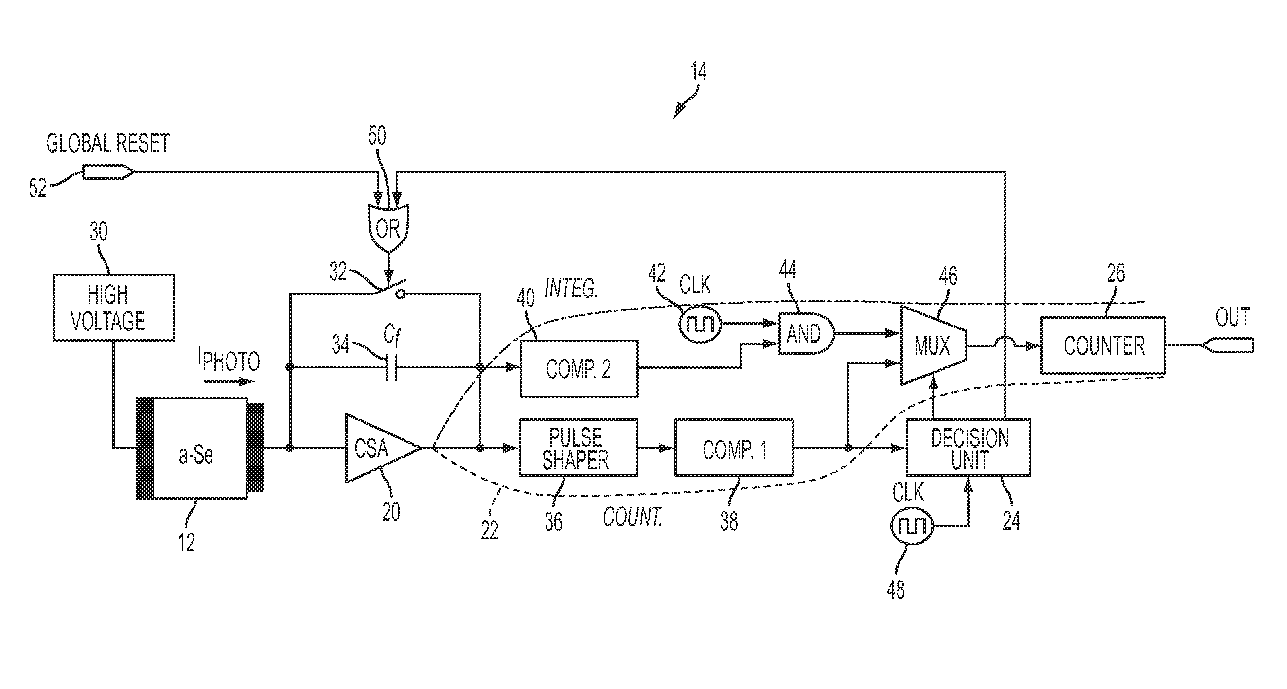
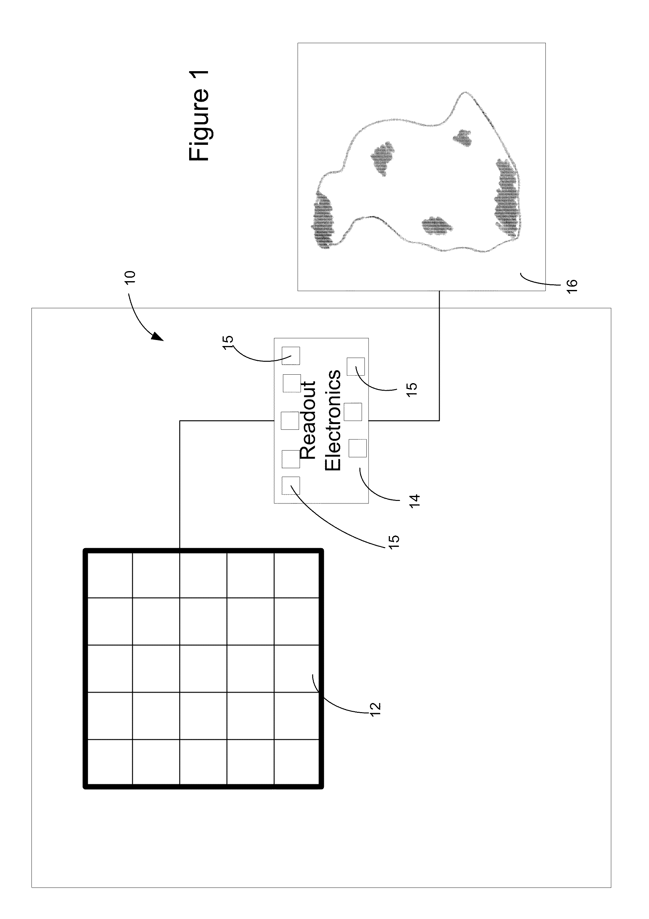
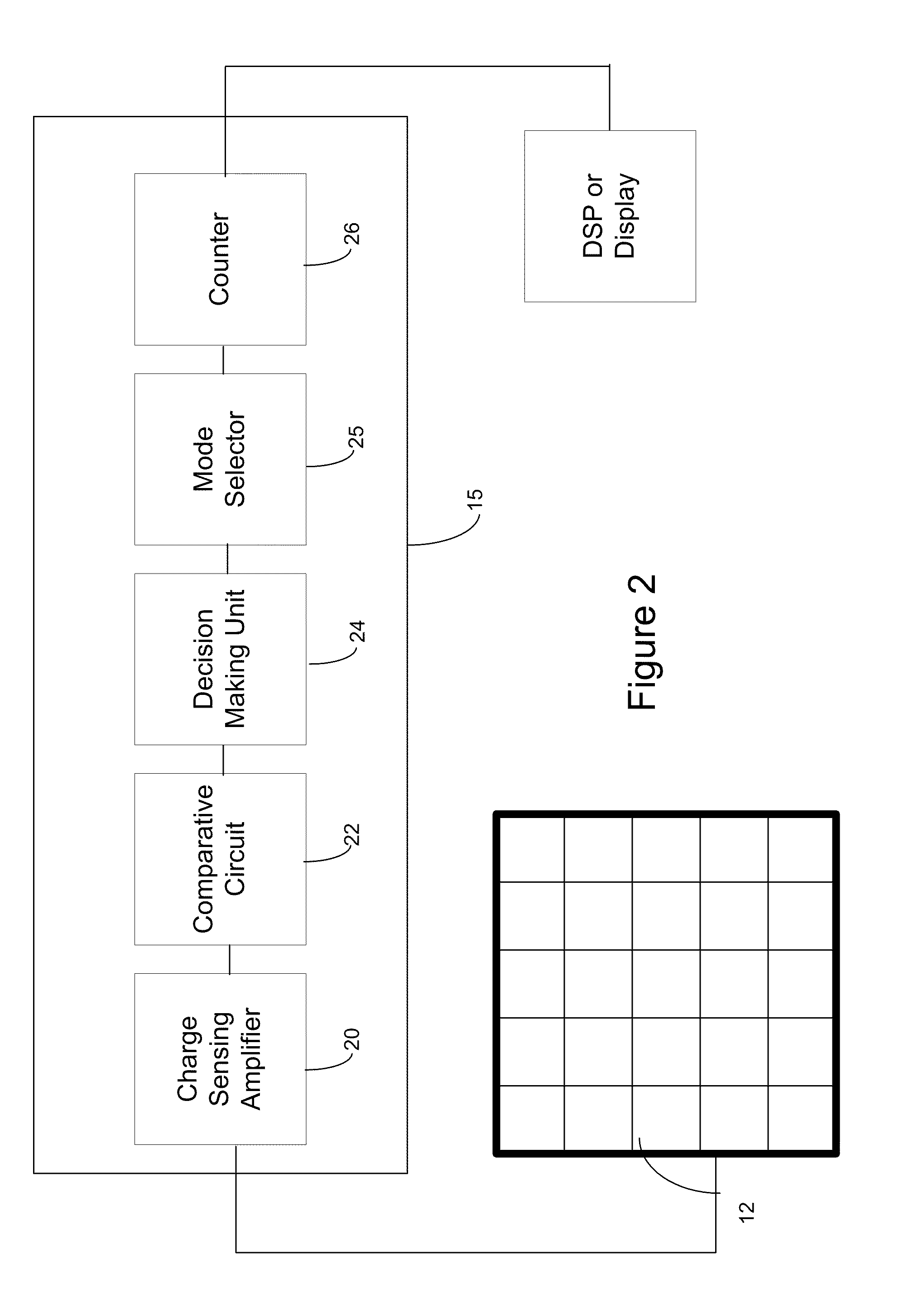
[0020]Turning to FIG. 1, a schematic diagram of a digital imaging system is shown. In the current embodiment, the digitization of the image is preferably performed per pixel. The imaging system, or detector, 10 includes a pixel array 12 which is connected to a set of readout electronics 14 which, in turn, is connected to a display 16. The set of readout electronics 14 include a set of digitizers 15, preferably equaling the number of pixels, in the pixel array 12. As will be understood, in operation, the pixel array 12 retrieves, or receives signals or readings which are then collected and transmitted to the readout electronics 14 which can then process the information, or signals, before transmitting this processed information to the display 16 for display and viewing an image 18 based on the processed information.
[0021]In a preferred embodiment of the system, for each pixel, there is an associated digitizer 15 in order to assist in determining the signals, or photons, which are bei...
PUM
 Abstract
Description
Claims
Application Information