Initial rotor position detection for permanent magnet synchronous motors

a synchronous motor and initial rotor technology, applied in the direction of motor/generator/converter stopper, electronic commutator, dynamo-electric converter control, etc., can solve the problem of increasing the machine size and cost of the motor drive, reducing the reliability of the system, and research suffer the same difficulty in detecting the rotor position at standstill. problems, to achieve the effect of smooth startup performance, fast detecting process, and high sensitivity to noise issues

Active Publication Date: 2010-07-22
RICHTEK TECH
View PDF6 Cites 59 Cited by
  • Summary
  • Abstract
  • Description
  • Claims
  • Application Information

AI Technical Summary

Benefits of technology

[0026]In the proposed apparatus and method, no ADCs are required to measure the motor currents. Besides, not only the rise times but also the fall times of the motor currents will be utilized for determining the initial rotor position angle at standstill. Therefore, higher sensitivity to noise issue can be obtained with compared to related arts. Furthermore, with generating twelve voltage vectors, thirty-degree resolution for the initial angle detection can be achieved for smoother startup performance. Another important feature of the present invention is that since the instant of the motor current free-wheeling to zero can be obtained with the fall-time detection, the next testing voltage vector can be applied just after the motor current drops to zero. Hence the fast detecting process can be achieved.

Problems solved by technology

However, these sensors increase the machine size and cost of the motor drive, and reduce the system reliability.
However, most of these researches suffer the same difficulty in detecting the rotor position at standstill.
If the initial rotor position at standstill cannot be exactly detected, the starting torque of the motor decreases, and temporarily reversed rotation may occur at starting, which is not allowed in some applications, such as hard disks.
However, this duration may cause the rotor slightly rotate and may also cause over-current conditions.
However, an ADC is still required with this method, and the determination of current change rate may have large variations due to the noise issue.
The accuracy of the rotor position detection may be reduced with scaling the terminal voltages due to the noise issue.
Besides, only sixty-degree resolution can be obtained with this method.
However, all the current methods for initial rotor position detection based on rise time measurement use single-ended amplifier circuits to detect the motor current, so that only the rise time, but not the fall time, of the motor current can be detected, and in consequence the time that the motor current drops to zero cannot be precisely determined.
As a result, a long detection time is needed at motor startup.

Method used


Image

  • Initial rotor position detection for permanent magnet synchronous motors
  • Initial rotor position detection for permanent magnet synchronous motors
  • Initial rotor position detection for permanent magnet synchronous motors

Examples


first embodiment

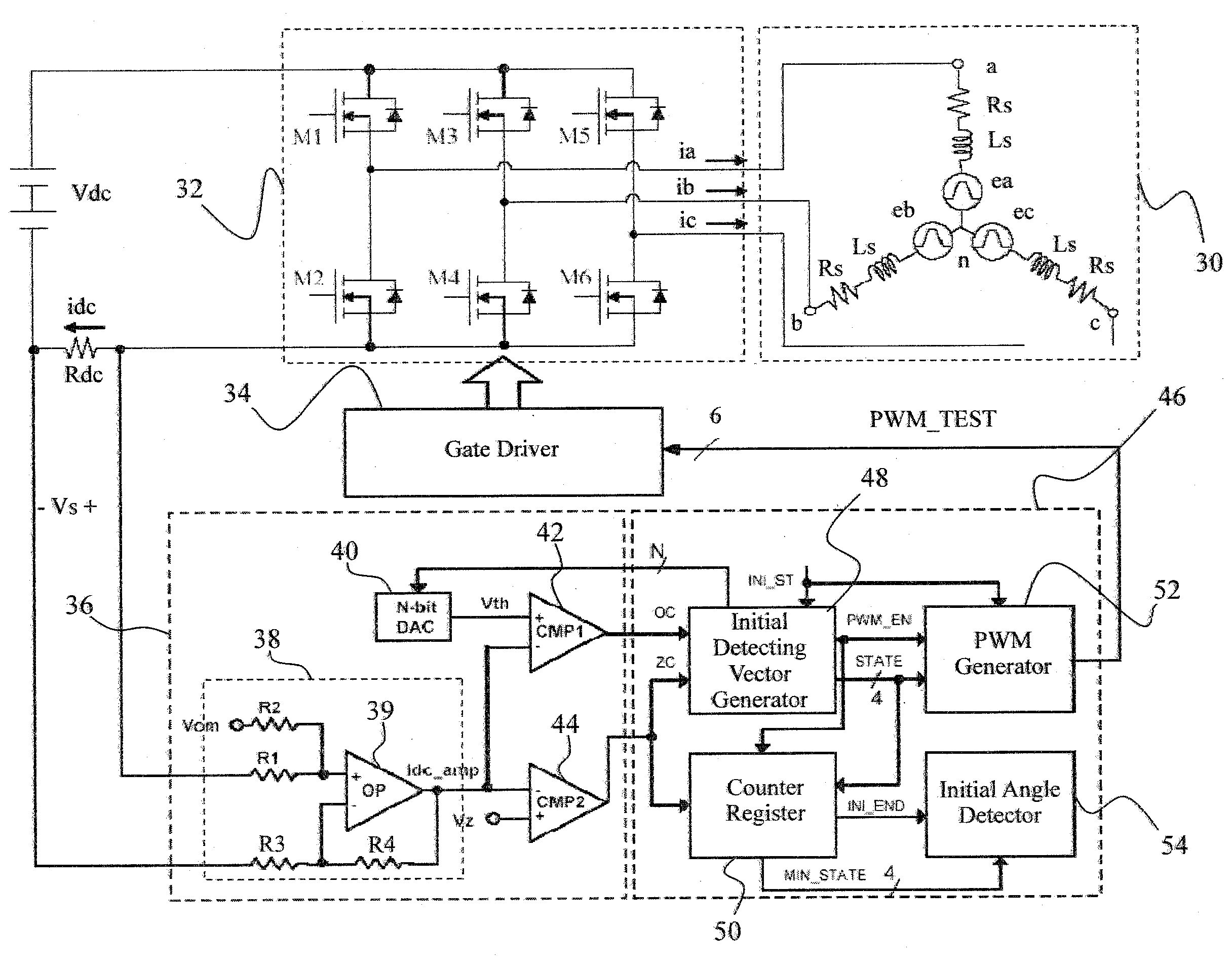
[0039]FIG. 6 is a circuit diagram of a first embodiment according to the present invention, in which a gate driver 34 switches power switches M1-M6 in a PWM inverter 32 according to a signal PWM_TEST provided by an internal digital initial angle detector 46 so as to apply different voltage vectors to a PMSM 30, a shunt resistor Rdc is coupled to the PMSM 30 for establishing a DC-link current idc related to a motor current of the PMSM 30 to be detected to generate a sensing signal Vs, an internal analog current processing circuit 36 generates an over-current signal OC and a zero-current signal ZC according to the sensing signal Vs, and the internal digital initial angle detector 46 generates the signal PWM_TEST according to the over-current signal OC and the zero-current signal ZC.

[0040]FIG. 7 is a waveform diagram of the circuit shown in FIG. 6. When the PMSM 30 is started from standstill, a starting signal INI_ST, as shown by the waveform 60, is provided to enable an initial detect...

second embodiment

[0044]FIG. 9 is a circuit diagram of a second embodiment according to the present invention. In addition to the PMSM 30, the inverter 32, the gate driver 34, the shunt resistor Rdc, and the internal analog current processing circuit 36 the same as those of FIG. 6, an internal digital initial angle detector 80 has the initial detecting vector generator 48 to provide the signal PWM_EN and the state signal STATE according to the over-current signal OC and the zero-current signal ZC. The PWM generator 52 in the internal digital initial angle detector 80 generates the signal PWM_TEST according to the signals PWM_EN and STATE to switch the voltage vector applied to the PMSM 30. A counter register 82 in the internal digital initial angle detector 80 detects the zero-current signal ZC to count the fall time of the motor current in the PMSM 30 under each of the voltage vectors. After obtaining the fall time corresponding to the presently applied voltage vector, the fall time is compared with...

fourth embodiment

[0046]FIG. 11 is a circuit diagram of a fourth embodiment according to the present invention. In addition to the PMSM 30, the inverter 32, the gate driver 34, and the shunt resistor Rdc the same as those of FIG. 6, this embodiment includes an internal analog current processing circuit 100 and an internal digital initial angle detector 102. The internal analog current processing circuit 100 includes the double-ended amplifier circuit 38 for amplifying the sensing signal Vs detected from the shunt resistor Rdc and adding the offset voltage Vcm to the sensing signal Vs so as to generate the amplified signal Idc_amp, the comparator 42 for comparing the voltage Vth with the amplified signal Idc_amp so as to generate the over-current signal OC, and the comparator 44 for comparing the amplified signal Idc_amp with the voltage Vz so as to generate the zero-current signal ZC. The voltage Vth is a constant in this embodiment. The initial detecting vector generator 48 in the internal digital i...


PUM


Abstract

An apparatus and method for use with a PMSM detect the fall time or the rise time and the fall time of a motor current in the PMSM under different voltage vectors when the PMSM is in start-up to determine an initial rotor position for the PMSM at standstill.

Description

FIELD OF THE INVENTION[0001]The present invention is related generally to permanent magnet synchronous motors and, more particularly, to initial rotor position detection for permanent magnet synchronous motors.BACKGROUND OF THE INVENTION[0002]References of related arts are listed in the following:[0003][1] P. P. Acarnley and J. F. Watson, “Review of position-sensorless operation of brushless permanent-magnet machines,” IEEE Trans. Ind. Electron., vol. 53, no. 2, pp. 352-362, April 2006;[0004][2] S. Nakashima, Y. Inagaki, and I. Miki, “Sensorless initial rotor position estimation of surface permanent-magnet synchronous motor,” IEEE Trans. Ind. Applicat., vol. 36, no. 6, pp. 1598-1603, November / December 2000;[0005][3] W. J. Lee and S. Ki Sul, “A new starting method of BLDC Motors without position sensor,” IEEE Trans. Ind. Applicat., vol. 42, no. 6, pp. 1532-1538, November / December 2006;[0006][4] Y. C. Chang and Y. Y. Tzou, “A new sensorless starting method for brushless DC motors with...

Claims


Application Information

Patent Timeline
Patent Type & Authority Applications(United States)
IPC IPC(8): H02P6/20H02P6/18
CPCH02P6/20H02P6/18
Inventor CHENG, KUANG-YAO
Owner RICHTEK TECH
Why Eureka
Try Eureka