Optical tomographic imaging apparatus

a tomographic imaging and optical tomography technology, applied in the field of optical tomographic imaging apparatus, can solve problems such as and achieve the effect of reducing the deformation of acquired images

Inactive Publication Date: 2010-07-22
CANON KK
View PDF10 Cites 25 Cited by
  • Summary
  • Abstract
  • Description
  • Claims
  • Application Information

AI Technical Summary

Benefits of technology

[0010]There is provided an optical tomographic imaging apparatus, according to the present invention, in which a beam emitted from a light source is split into a first measuring beam and a first reference beam, the first measuring beam being guided to an inspection object whereas the first reference beam being allowed to travel on a beam path having first beam path length changing unit thereon, wherein a tomographic image of the inspection object is acquired by using an interference light between a return beam of the first measuring beam reflected on or scattered from the inspection object and the first reference beam traveling on the beam path having the first beam path length changing unit thereon, the optical tomographic imaging apparatus comprising: an optical interferometer which splits the beam emitted from one of the light source and another light source into a second measuring beam and a second reference beam so as to guide the second measuring beam to a position, at which movement of the inspection object is detected, and further, allow the second reference beam to travel on a beam path having second beam path length changing unit thereon, thus detecting moving amount of the inspection object by using an interference light between a return beam of the second measuring beam reflected on or scattered from the movement detection position of the inspection object and the second reference beam traveling on the beam path having the second beam path length changing unit thereon; and positional misplacement correcting unit provided on the beam path of the first reference beam independently of the first beam path length changing unit, for changing the beam path length of the first reference beam based on the moving amount of the inspection object detected by the optical interferometer, so as to reduce deformation of the tomographic image of the inspection object caused by a positional misplacement at the movement detection position of the inspection object, wherein the beam path length of the first reference beam by the positional misplacement correcting unit and the beam path length of the second reference beam by the second beam path length changing unit can be changed by a mechanism.
[0014]The present invention can implement the optical tomographic imaging apparatus capable of further reducing the deformation of the acquired image in the depth direction of the eye ball caused by the back and forth motion of the eye ball during the measurement.

Problems solved by technology

Since the OCT device forms an image by scanning, there arises a problem that an involuntary motion of an eye ball called an involuntary eye movement of a human eye ball or a back and forth motion of an eye ball including the whole head may deform an acquired image.

Method used


Image

  • Optical tomographic imaging apparatus
  • Optical tomographic imaging apparatus
  • Optical tomographic imaging apparatus

Examples


embodiments

[0030]Embodiments according to the present invention will be described below.

first embodiment

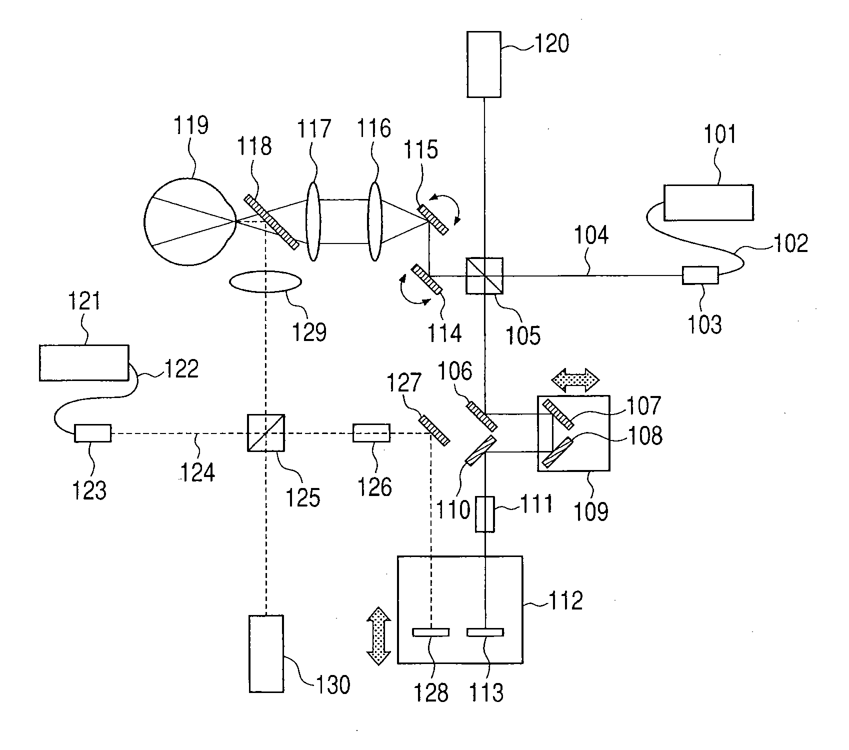
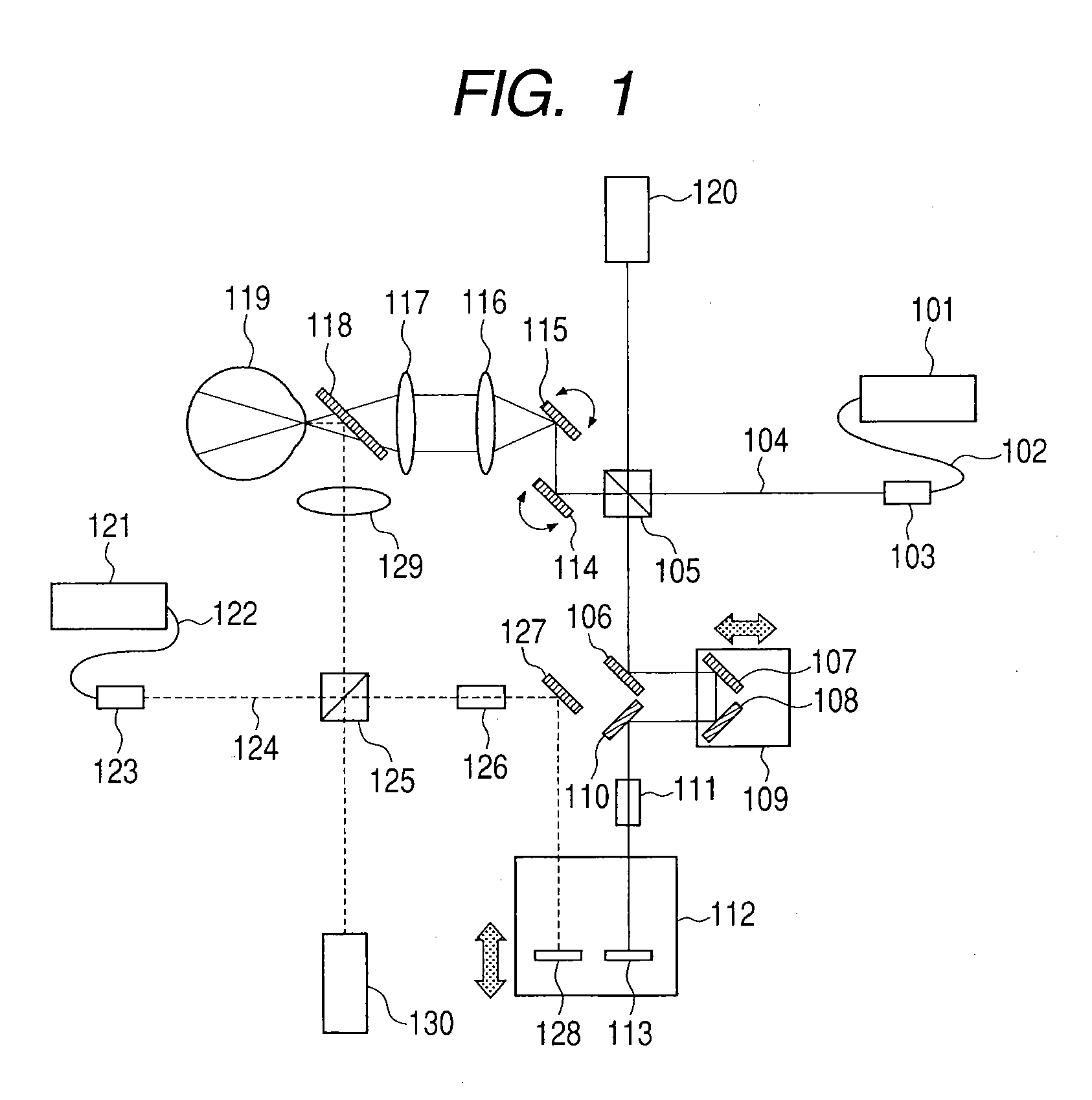
[0031]In a first embodiment, a description will be given of the configuration of an OCT device, to which the present invention is applied. FIG. 1 is a diagram conceptually illustrating the entire configuration of the OCT device in the present embodiment. In FIG. 1, there are illustrated a low coherent light source 101 for fundus tomography, an optical fiber 102, a fiber collimator 103, a fundus photographing beam path 104, a beam splitter 105, a mirror 106, a first reference mirror 107, a second reference mirror 108, a reference beam path length adjusting stage 109, a mirror 110, a dispersion compensating glass 111, a tracking stage 112, a fundus tracking mirror 113, a galvano scanner X 114, a galvano scanner Y 115, a first lens 116, a second lens 117, a dichroic mirror 118, and an eye to be inspected 119. Examples of an OCT include a Michelson interferometer. Examples of an interferometer for detecting a back and forth motion of an eye ball also include a Michelson interferometer. ...

second embodiment

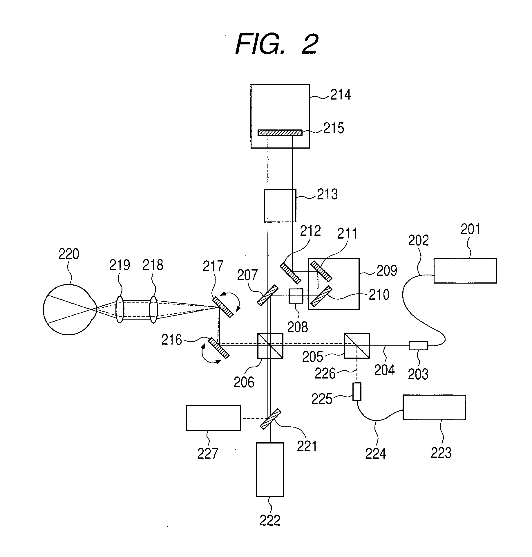
[0039]A second embodiment exemplifies an OCT device having a configuration in which a beam path of a low coherent beam interferometer for detecting a back and forth motion of an eye ball is shared by an OCT device for fundus tomography. FIG. 2 is a diagram conceptually illustrating the entire configuration of an OCT device in the present embodiment. In FIG. 2, there are illustrated a low coherent light source 201 for fundus tomography, an optical fiber 202, a fiber collimator 203, a fundus photographing beam path 204, a beam splitter 205, another beam splitter 206, a dichroic mirror 207, a dispersion compensating glass 208, a reference beam path length adjusting stage 209 for a fundus, a reference beam path length adjusting mirror 210, another reference beam path length adjusting mirror 211, a mirror 212, a dispersion compensating glass 213, a tracking stage 214, a tracking mirror 215, a galvano mirror X 216, a galvano mirror Y 217, a first lens 218, a second lens 219, an eye to be ...


PUM


Abstract

In an optical tomographic imaging apparatus in which a tomographic image is acquired using an interference light between a return beam of a first measuring beam and a first reference beam traveling on a beam path having first beam path length changing unit thereon, an optical interferometer detects movement of the inspection object by using an interference light between a return beam of a second measuring beam from a movement detection position and a second reference beam traveling on a beam path having second beam path length changing unit thereon; and positional misplacement correcting unit changes the beam path length of the first reference beam based on the moving amount detected by the optical interferometer, wherein the beam path lengths of the two reference beams can be changed by a mechanism, thus further reducing deformation of an acquired image in an eye ball depth direction caused by a back and forth motion.

Description

BACKGROUND OF THE INVENTION[0001]1. Field of the Invention[0002]The present invention relates to an optical tomographic imaging apparatus and, more particularly, to an optical tomographic imaging apparatus for use in opthalmological treatment or the like.[0003]2. Description of the Related Art[0004]Various kinds of optical equipment are currently used as opthalmological equipment. Among them, there are various kinds of equipment used for observing an eye. For example, as such equipment are used an anterior ocular segment photographing device, a fundus camera, and a scanning laser opthalmoscope (abbreviated as “an SLO”). Otherwise, there are used a low coherent optical tomographic imaging apparatus (optical tomographic imaging apparatus) and the like with an optical coherence tomography (abbreviated as “OCT”) device (hereinafter referred to as “an OCT device”). Among them, the OCT device can obtain a tomographic image of a fundus in a high resolution, and therefore, it has become ind...

Claims


Application Information

Patent Timeline
Patent Type & Authority Applications(United States)
IPC IPC(8): G01B11/10G01B11/02A61B3/14
CPCA61B3/102G01B9/02007G01B9/02091G01B9/02068G01B9/02077G01B9/02083G01B2290/45
Inventor UTSUNOMIYA, NORIHIKO
Owner CANON KK
Why Eureka
Try Eureka