[0007]The primary objective of the present invention is to provide a fiber sensing system with self-detection mechanism which uses
tunable laser as source of light in order to provide better reliability for wide-range sensing system. When there is an error occurred within the
network connection architecture, the self-detection mechanism will execute sensing and restoration mechanism immediately.
[0008]Another objective of the present invention is to provide a fiber sensing system with self-detection mechanism that can greatly enhance
survivability and sensing capacity of
all fiber sensors, so that when a fault point caused by
environmental change within the fiber, it will not effect the overall operation of the sensing mechanism. The application of fiber sensor can also reduce cost and complexity of the overall fiber
network topology.
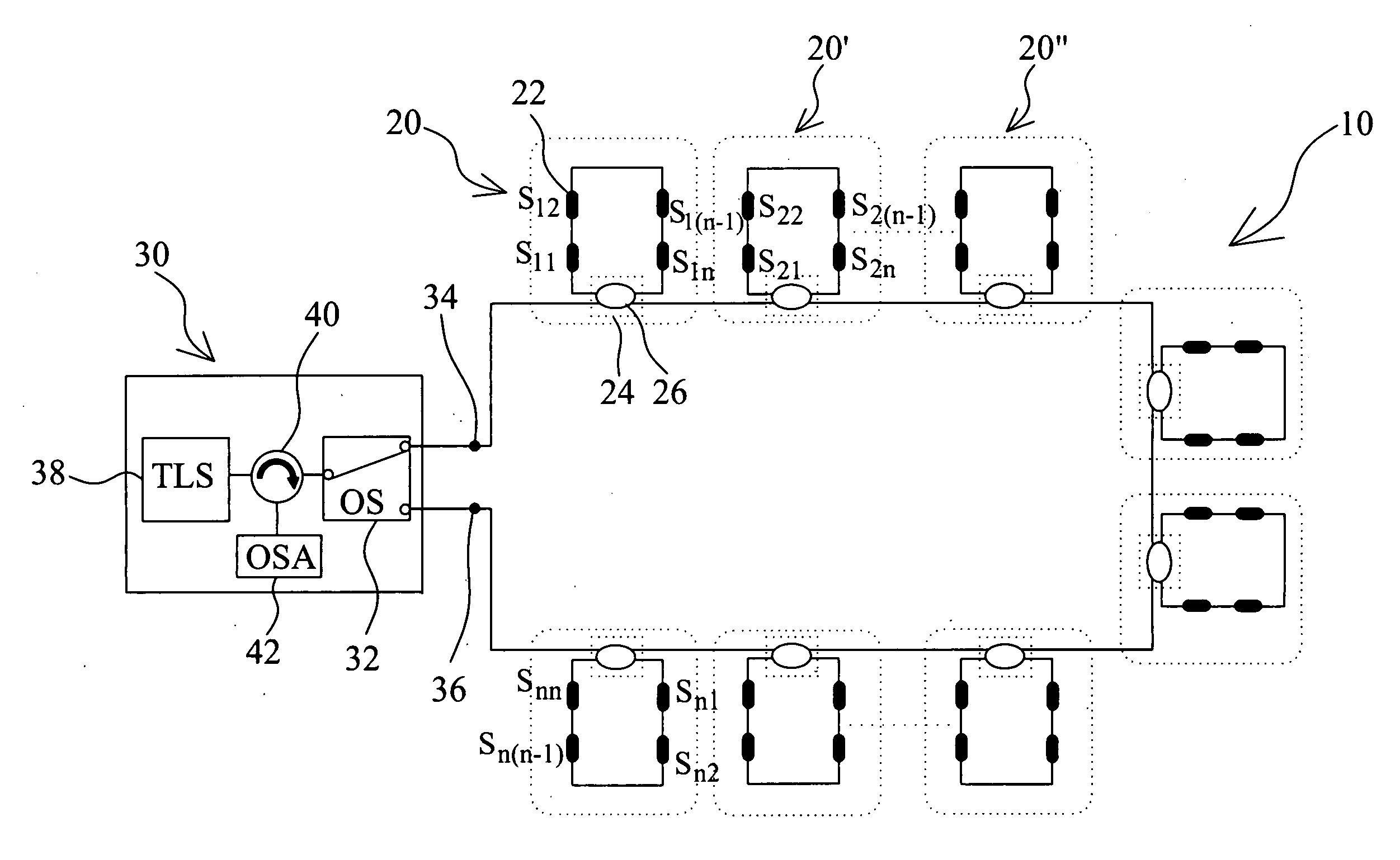
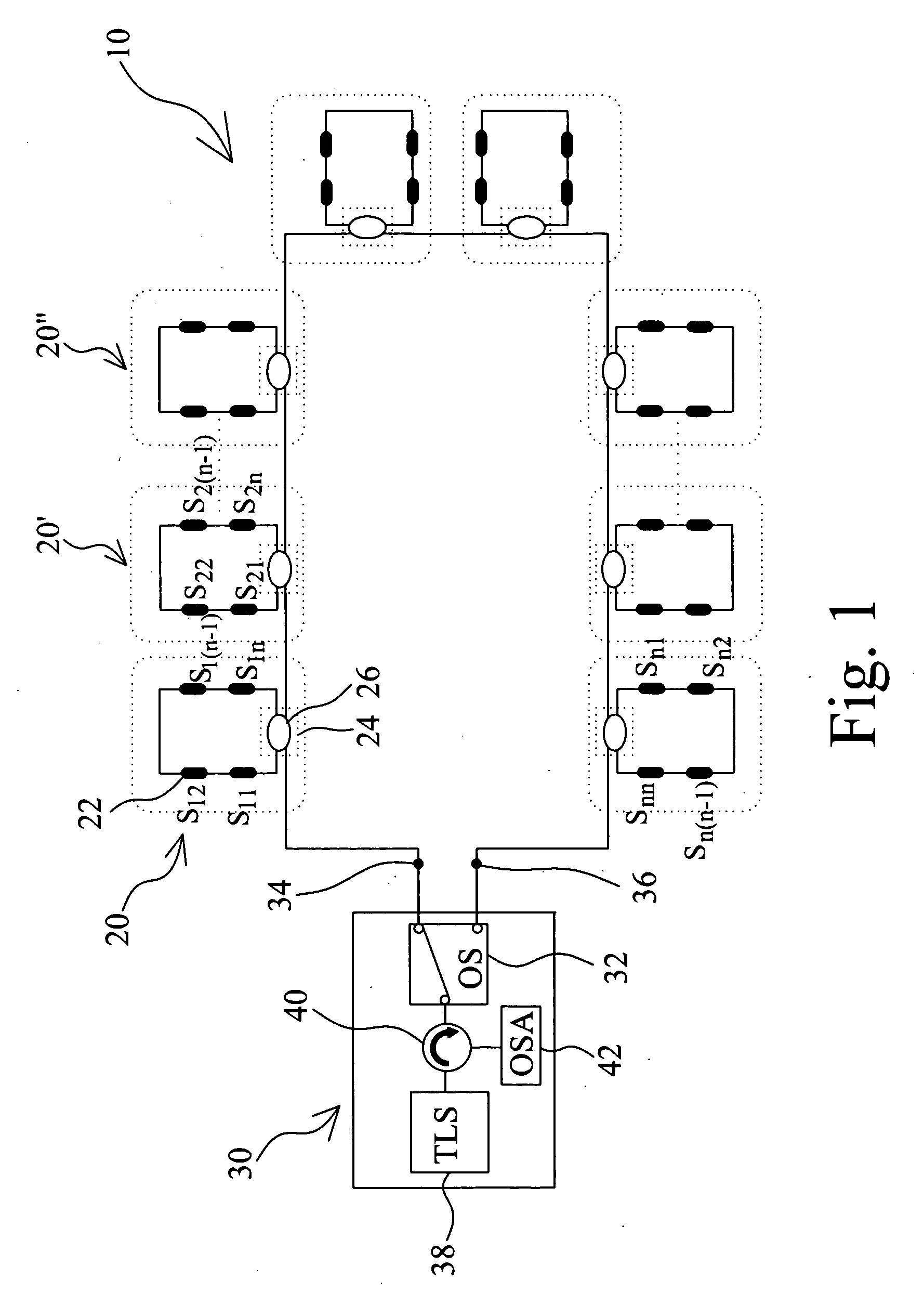
[0009]In order to realize objectives mentioned above, the fiber sensing system with self-detection mechanism of the present invention comprises a primary ring architecture and a central office. The primary ring architecture is formed by multiple secondary ring architectures which are connected to each other serially to form a primary loop. The secondary ring architecture includes at least two fiber sensors which can receive and reflect light source
signal and a remote node. The remote node has an
optical coupler which allows the light source
signal to pass the fiber sensor to form a
secondary loop, additionally the remote node can connect to adjacent secondary ring architectures. The primary function of central office is to provide and monitor the light source signal. The central office also has an
optical switch wherein the
optical switch has two outputs that connect to the primary ring architecture, forming a first path and a second path respectively. The
optical switch can switch the traveling of the light source signal between the first path and the second path. The central office also comprises a tunable
laser light source and an
optical circulator, where the tunable
laser light source emits the light source signal to the optical switch through the
optical circulator, the optical switch can then switch the path of the light source signal to either first path or second path. The central office further includes an
optical spectrum analyzer which is connected to the
optical circulator. The fiber sensor mentioned above is
Fiber Bragg
Grating (FBG). The tunable
laser light source is first dispersed into multi-light source and delivered to each remote node, then to the fiber sensor through the
optical coupler on the remote node. Since the fiber sensor has reflective ability, all light source signal sent by the tunable
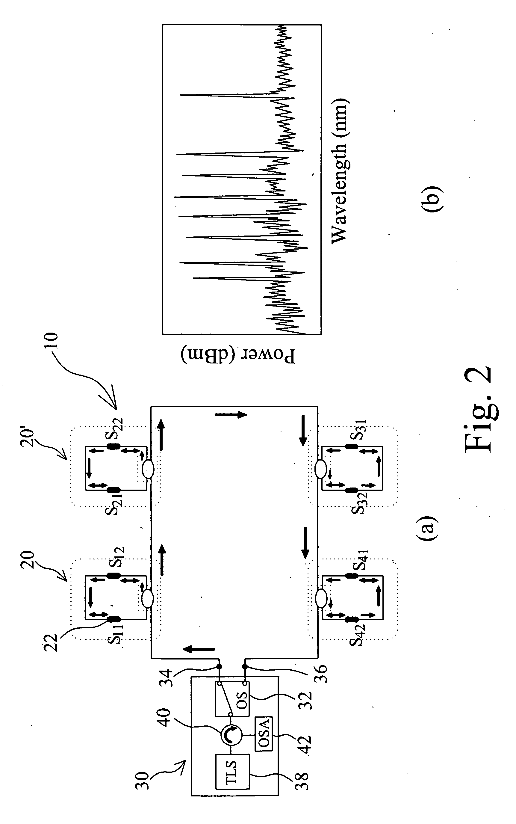
laser light source will be detected and measured by the fiber sensor. If there is no fault point on the primary ring architecture and the secondary ring architecture, central office can detect all signals reflected by the fiber sensor. The fiber sensing system with self-detection mechanism of the present invention utilizes central office to control the secondary ring architecture formed by the fiber sensor, the remote node and the optical coupler primarily, the secondary ring architecture is connected serially to form a primary ring architecture. The central office has a tunable
laser light source, the tunable
laser light source is first dispersed into multi-light source and delivered to each remote node, then to the fiber sensor through the optical coupler on the remote node. Since the fiber sensor has reflective ability, all light source signal sent by the tunable laser light source will be detected and measured by the fiber sensor. If there is no fault point on the primary ring architecture and the secondary ring architecture, central office can detect all signals reflected by the fiber sensor and produce a spectrum. Not only does the present invention provides wider-range and multi-point detection, it also greatly reduce the manufacture cost of the optical network.

