Plasma processing apparatus and plasma processing method

a processing apparatus and plasma technology, applied in the field of plasma processing apparatus and plasma processing method, can solve the problems of increasing cost, reducing the use amount of dielectric members, and deemed uneconomical, so as to reduce the area of the dielectric members exposed, reduce the amount of dielectric members, and avoid metal contamination from the inner surface of the processing chamber

Inactive Publication Date: 2010-07-22
TOKYO ELECTRON LTD +1
View PDF15 Cites 16 Cited by
  • Summary
  • Abstract
  • Description
  • Claims
  • Application Information

AI Technical Summary

Benefits of technology

[0023]In accordance with the present invention, since the plasma can be excited by the electromagnetic wave (conductor surface wave) propagated along the surface wave propagating section installed around the dielectric member, the used amount of the dielectric member can be greatly reduced. Furthermore, by reducing the area of the dielectric member exposed to the inside of the processing chamber, damage or etching of the dielectric member due to overheating thereof can be suppressed, and metal contamination from the inner surface of the processing chamber can be avoided. Further, since the decrease of the exposed area of the dielectric member results in an increase of the exposed area of the cover, the gas supply holes can be readily formed in the metal cover. By arranging the gas supply holes in the entire bottom surface of the metal cover, the processing gas can be uniformly supplied onto the entire processing surface of the substrate in a shower plate-like manner. In addition, when a microwave of about 915 MHz is used as an electromagnetic wave having a frequency equal to or less than about 2 GHz, for example, a minimum electron density for obtaining stable plasma having a lower electron temperature can be reduced to about 1 / 7 of an electron density in case of using a microwave of 2.45 GHz. Thus, plasma suitable for plasma processes can be obtained under various conditions wider than those of the conventional case, and the wide range of applications of the processing apparatus can be greatly improved. As a result, it becomes possible to perform a plurality of consecutive processes under different processing conditions in a single processing apparatus, so that high-quality products can be manufactured in a short period of time with low cost.

Problems solved by technology

If, however, the exposed area of the dielectric member is set to be substantially same as the area of the processing surface of the substrate as in the conventional plasma processing apparatus, a great amount of dielectric member is required and thus is deemed to be uneconomical.
Especially, with the recent trend for the scale-up of the substrate, a greater amount of dielectric member needs to be used, resulting in an increase of cost.
Furthermore, in case that the dielectric member is installed on the entire bottom surface of the cover of the processing chamber, it becomes difficult to uniformly supply the processing gas onto the entire substrate processing surface.
For example, if Al2O3 is used as the dielectric member, it is more difficult to form gas supply holes in the dielectric member than in the metal cover.
Thus, the gas supply holes are provided only at exposed positions of the cover, so that uniform supply of the processing gas onto the entire processing surface of the substrate in a shower plate-like manner becomes difficult.

Method used


Image

  • Plasma processing apparatus and plasma processing method
  • Plasma processing apparatus and plasma processing method
  • Plasma processing apparatus and plasma processing method

Examples


modification examples

[0189]Below, other embodiments of the plasma processing apparatus 1 will be explained. Parts identical with those described in the plasma processing apparatus 1 with reference to FIG. 1 and the like will be assigned like reference numerals, and redundant description will be omitted.

first modification example

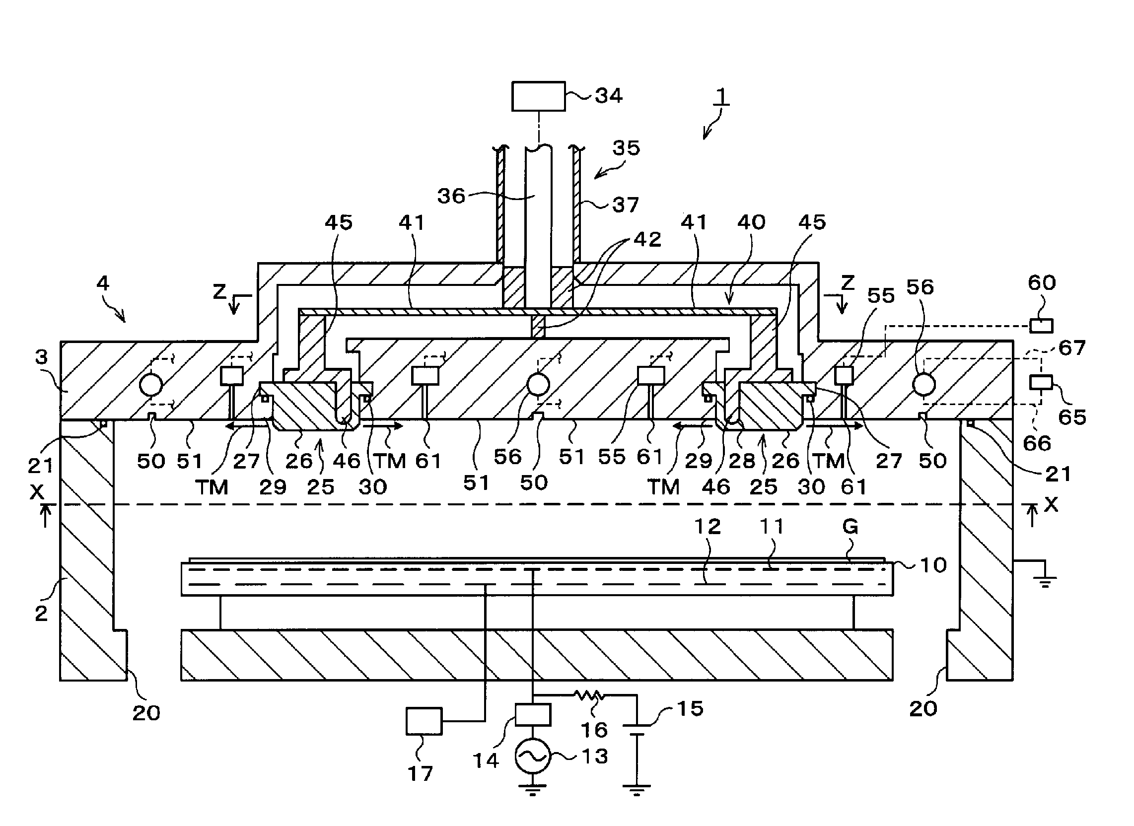
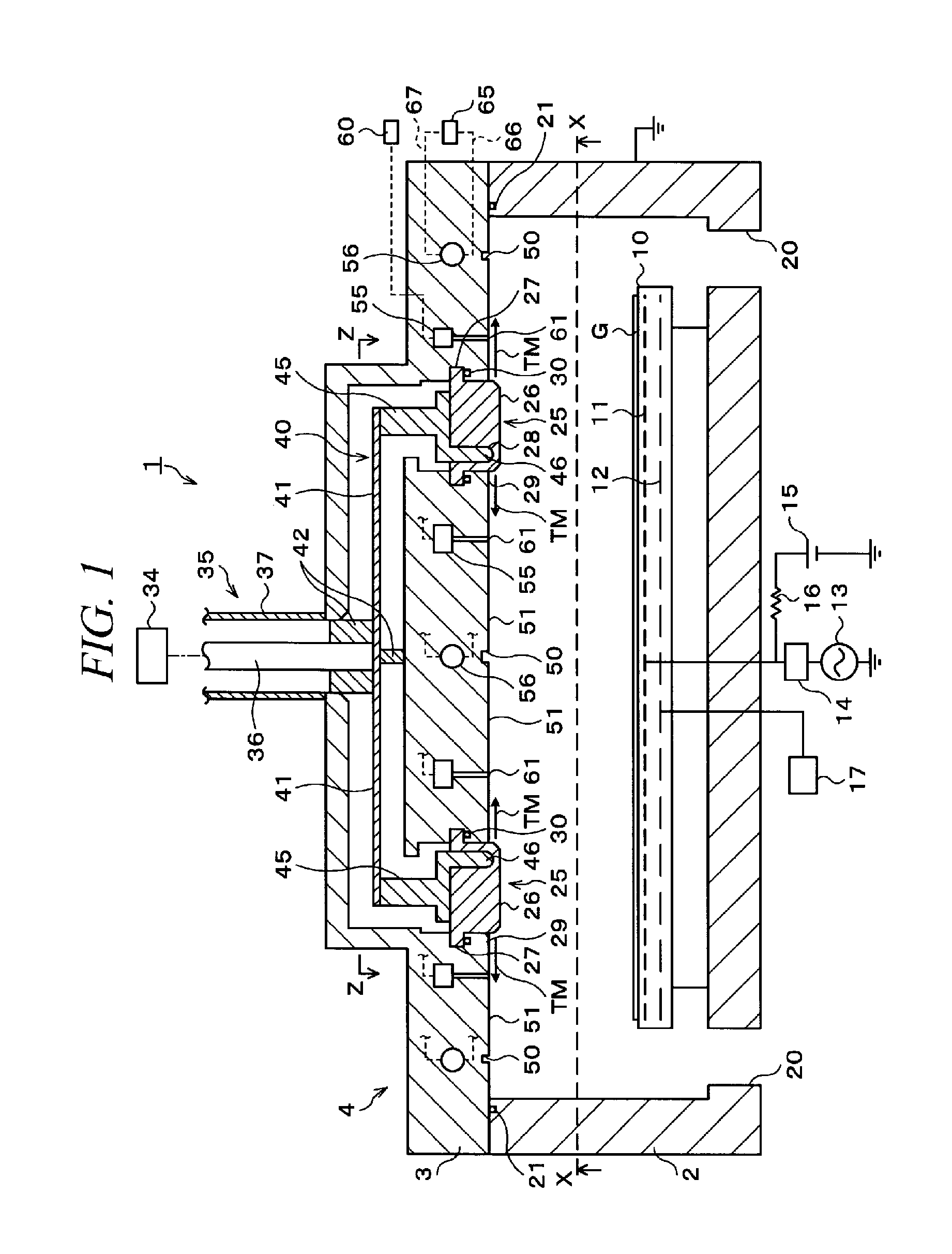
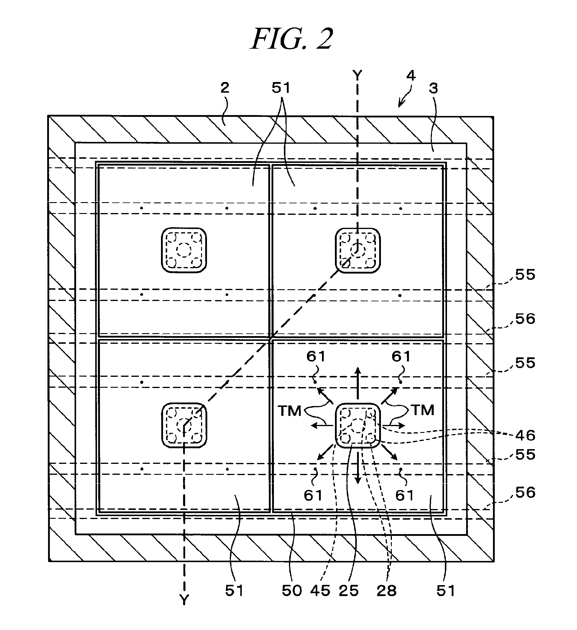
[0190]FIG. 15 is a longitudinal cross section view of a plasma processing apparatus 1 in accordance with a first modification example (taken along a line Y-Y of FIG. 16). FIG. 16 is a bottom view (taken along a line X-X of FIG. 15) of a cover 3 included in the plasma processing apparatus 1 in accordance with the first modification example. FIG. 17 is a transversal cross section view of a top part of the cover 3 taken along a line Z-Z of FIG. 15.

[0191]The plasma processing apparatus 1 in accordance with this first modification example has a configuration in which a plate-shaped metal electrode 70 is installed on a bottom surface of each of four plate-shaped dielectric members 25 made of, for example, Al2O3. The lower end of a metal rod 45 vertically inserted through the cover 3 and the dielectric member 25 is installed at the center of the metal electrode 70. The upper end of the metal rod 45 is suspended from the top surface of the cover 3 by a spring 71, and the dielectric member 2...

second modification example

[0197]FIG. 18 is a longitudinal cross section view illustrating a schematic configuration of a plasma processing apparatus 1 in accordance with a second modification example. FIG. 19 is a transversal cross section view of a top part of a cover 3 taken along a line Z-Z of FIG. 18.

[0198]The plasma processing apparatus 1 in accordance with the second modification example basically has the same configuration as that of the plasma processing apparatus 1 in accordance with the first modification example described with reference to FIGS. 15 to 17 excepting that an end surface 74′ of a distribution waveguide 74 is formed in a lower position and an internal conductor 36 is connected to the cover 3 via a dielectric member 42 serving as an impedance matching member. The plasma processing apparatus 2 in accordance with this second modification example can also acquire the same function and effect as obtained by the plasma processing apparatus 1 in accordance with the first modification example ...


PUM

PropertyMeasurementUnit
frequencyaaaaaaaaaa
roughnessaaaaaaaaaa
frequencyaaaaaaaaaa

Abstract

A plasma processing apparatus capable of reducing the use amount of a dielectric member is provided. The plasma processing apparatus 1 includes a metal processing chamber 4 configured to accommodate therein a substrate G to be plasma-processed; an electromagnetic wave source 34 that supplies an electromagnetic wave necessary to excite plasma in the processing chamber 4; one or more dielectric members 25 provided on a bottom surface of a cover 3 of the processing chamber 4 and configured to transmit the electromagnetic wave supplied from the electromagnetic wave source 34 into the inside of the processing chamber 4, a portion of each dielectric member 25 being exposed to the inside of the processing chamber 4; and a surface wave propagating section 51 installed adjacent to the dielectric member 25 and configured to propagate the electromagnetic wave along a metal surface exposed to the inside of the processing chamber 4.

Description

TECHNICAL FIELD[0001]The present invention relates to a plasma processing apparatus and a plasma processing method for performing a process such as a film formation on a substrate by exciting plasma.BACKGROUND ART[0002]In a manufacturing process of, for example, a LCD device or the like, there has been used a plasma processing apparatus which performs a CVD (Chemical Vapor Deposition) process, an etching process or the like on a LCD substrate (glass substrate) by exciting plasma in a processing chamber by using microwaves. Known as such a plasma processing apparatus is an apparatus which supplies a microwave to a dielectric member provided on an inner surface of the processing chamber from a microwave source through a coaxial waveguide or a waveguide and excites a gas supplied into the processing chamber to plasma by using the energy of the microwave.[0003]Recently, along with the scale-up of the substrate and so forth, the plasma processing apparatus is also getting bigger. If the ...

Claims


Application Information

Patent Timeline
Patent Type & Authority Applications(United States)
IPC IPC(8): H05H1/46C23C16/511
CPCC23C16/511H01J37/32192H01J37/32266H05H1/46B05C13/00H01L21/205H01L21/3065
Inventor HIRAYAMA, MASAKIOHMI, TADAHIROHORIGUCHI, TAKAHIRO
Owner TOKYO ELECTRON LTD
Why Eureka
Try Eureka