
Power management in low power wireless link

a low-power wireless link and power management technology, applied in power management, loudspeaker spatial/construction arrangement, transmission, etc., can solve the problems of waste of power by devices with overhead current in a particular setup, and achieve the effect of influencing the speed of power level adjustment, reducing the effect of power level change, and large intended power level changes

Active Publication Date: 2010-07-22
OTICON
View PDF13 Cites 46 Cited by
  • Summary
  • Abstract
  • Description
  • Claims
  • Application Information

AI Technical Summary

Benefits of technology

[0011]This has the advantage of enabling an adaptation of the power consumption to the current needs. In an embodiment, a minimization of power consumption of the link is enabled.
[0024]In an embodiment, the actions of regulating the power level of the transmitter of the transmitting device is performed after a delay corresponding to the action in question, the delay possibly depending on the current power level, and / or the intended future power level, and / or a value and / or a rate of change of the link quality measure. A fast rate of change and / or a relatively large intended change in power level (e.g. more than one power level step) can e.g. result in a low or no delay in the consequent regulation.
[0025]In an embodiment, the link quality measure is averaged over time. By adjusting the time over which the link quality is averaged, the speed of reaction of the power level adjustment can be influenced, an increased averaging time resulting in a reduced speed of reaction and vice versa.
[0037]In a first aspect, the partial power down mode at least comprises a power-down of the components related to the wireless link (e.g. the transceiver). In an embodiment, ONLY the components related to the wireless link are powered down during a partial power-down. In an embodiment, the partial power down mode comprises a power-down of other components of the communication device related to the primary functionality of the device, e.g. main power consuming components (e.g. amplifier(s), signal processor(s), microphone(s), display(s), etc.). In an embodiment, ‘partial power down’ is taken to mean that the power consumption of the functional entity of the device is reduced substantially compared to a normally operating state of the device, such as to 10% of normal, such as to 5% of normal, such as to 1% of normal.
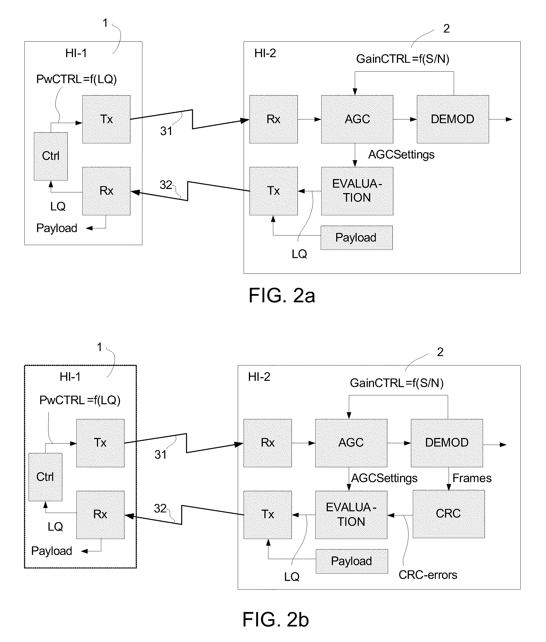
[0042]In an embodiment, the measure of link quality (LQ) is e.g. based on the signal strength of the received signal and / or its bit error rate and / or the gain-settings of the receiver (e.g. of an automatic gain control (AGC) unit) of the receiving (or transmitting) device. An advantage of using an AGC-setting and / or a signal strength of the received signal as opposed to a bit error rate is a faster indication (the determination of a bit error rate is dependent on the reception of a number of bits (e.g. arranged in frames), thus requiring a corresponding amount of time). Preferably the measures are combined to get a link quality measure providing ‘the best of several worlds’. In an embodiment, the measure of the quality of the link is based on the gain of an automatic gain control (AGC) unit necessary to achieve a predefined signal to noise ratio (S / N) or bit error rate (BER) of the received signal. In an embodiment, the measure of the quality of the link is additionally based on field strength of the received signal.
[0049]In an embodiment, the transmitting communication device is adapted to adjust the transmit power in a number of predefined (normal) levels between a minimum level and a maximum level. In an embodiment, the communication system is adapted to provide that a default power setting (e.g. after reset or power-up) of the transmitting communication device is the highest (maximum) power level. This has the advantage of providing the best conditions for establishing a connection to the other communication device, e.g. during startup (e.g. after a full or partial power-down). If, after startup, no link can be established at the maximum power level (indicating that the device is outside the Typical zone for operation relative to the other device), it is checked whether a link can be established at an extremely low level. Thereby it can be concluded, whether the device is in a VeryClose zone or a VeryFar zone relative to the other device (or alternatively that the other device is not powered up). In an embodiment, the power levels are equidistant on a linear scale. In an embodiment, the power levels are equidistant on a logarithmic scale (in dB). In an embodiment, the steps between neighboring power levels increase from the highest to the lowest level (e.g. in absolute terms or in logarithmic terms).

Problems solved by technology

The overhead in current in a particular setup represents a waste of power for those devices.

Method used


Image

  • Power management in low power wireless link
  • Power management in low power wireless link
  • Power management in low power wireless link

Examples


Embodiment Construction

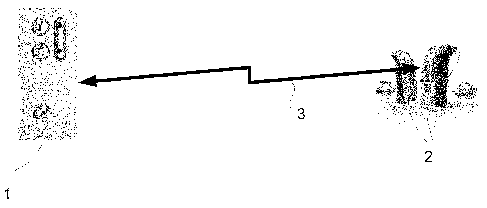
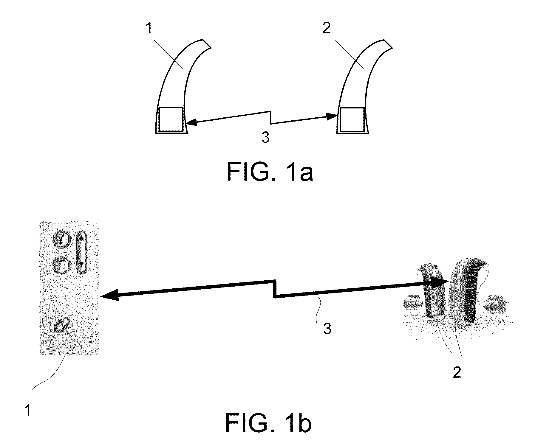
[0079]FIG. 1 generally illustrates a wireless link 3 between first and second communication devices 1, 2. Applications of the present invention include the wireless communication between two body-worn, low power communication devices, e.g. two hearing instruments (cf. e.g. FIG. 1a) or between an audio selection device (audio gateway) and one or more hearing instruments (cf. e.g. FIG. 1b). Alternatively, the communication devices 1, 2 could be a pair of headphones, a pair of hearing protective ear plugs, a mobile telephone and a listening device, an entertainment device (e.g. a music player) and a listening device, etc.

[0080]In the following (FIG. 1a), an embodiment of the invention is exemplified by a binaural hearing aid system comprising two hearing instruments adapted to be worn at and / or in each ear of a user, the hearing instruments having a wireless link between them for exchanging control or status information (and possibly audio signals) between them. In an embodiment, no au...


PUM


Abstract

The invention relates to a communication system comprising a first and a second communication device, each comprising transmit and receive units for establishing a wireless link between the devices, wherein the first device is a portable listening device. The invention further relates to a method, a data processing system and a medium. The object of the present invention is to control power consumption in a short range wireless link. The problem is solved in that at least the first communication device comprises a control unit for dynamically adjusting the transmit power of its transmit unit based on a measure of the quality of the link, wherein the system is adapted to use the dynamic transmit power regulation to implement a partial power-down mode of the system, when the two communication devices are expected NOT to be in a normal use, wherein the partial power-down mode at least comprises a power-down of the components related to the wireless link. This has the advantage of enabling an adaptation of the power consumption to the current needs. The invention may e.g. be used for wireless communication between (portable) low power devices, e.g. between a pair of hearing instruments.

Description

TECHNICAL FIELD[0001]The present invention relates to low power wireless communication, and especially to power management, including power regulation. The invention relates specifically to a communication system comprising a first and a second communication device, each comprising transmit and receive units for establishing a wireless link between the devices.[0002]The invention furthermore relates to a method of controlling power consumption in a wireless link between two communication devices.[0003]The invention furthermore relates to a data processing system and to a tangible computer-readable medium.[0004]The invention may e.g. be useful in applications such as wireless communication between (portable) low power devices, e.g. between a pair of hearing instruments.BACKGROUND ART[0005]First generation wireless link systems for portable listening devices, such as hearing aids, have typically been based on fixed transmitted power between the devices. The transmitter current is, e.g...

Claims


Application Information

Patent Timeline
Patent Type & Authority Applications(United States)
IPC IPC(8): H04B17/00
CPCH03F2200/451H04R25/552H04R25/70H04W52/10H04W52/245H04W52/265H04W52/52
Inventor LERKE, PETER DAM
Owner OTICON
Learn More