Battery Control Device

Active Publication Date: 2010-07-22
HITACHI VEHICLE ENERGY
View PDF3 Cites 134 Cited by
  • Summary
  • Abstract
  • Description
  • Claims
  • Application Information

AI Technical Summary

Benefits of technology

[0015]According to the present invention it is possible to select, from among a plurality of resistance value tables, a resist

Problems solved by technology

However, with the prior art type battery control device described above, there has been the problem that it is not possible to determine the battery life accurately, since no consideration is taken of the state of h

Method used


Image

  • Battery Control Device
  • Battery Control Device
  • Battery Control Device

Examples


Example

[0025]In the embodiments explained below, the present invention is explained by giving examples of use thereof as a drive power supply for a drive system for a large sized hybrid vehicle. Such a large sized hybrid vehicle may be a public vehicle such as a hybrid bus or the like, or a cargo vehicle such as a hybrid truck or the like. The embodiment below will be described in terms of a hybrid bus. Moreover, the structure of the embodiment described below is not limited to application to a hybrid automobile; it may also be applied to an electric automobile or a hybrid train or the like, or indeed to any machine or device whose source of electrical power is a battery.

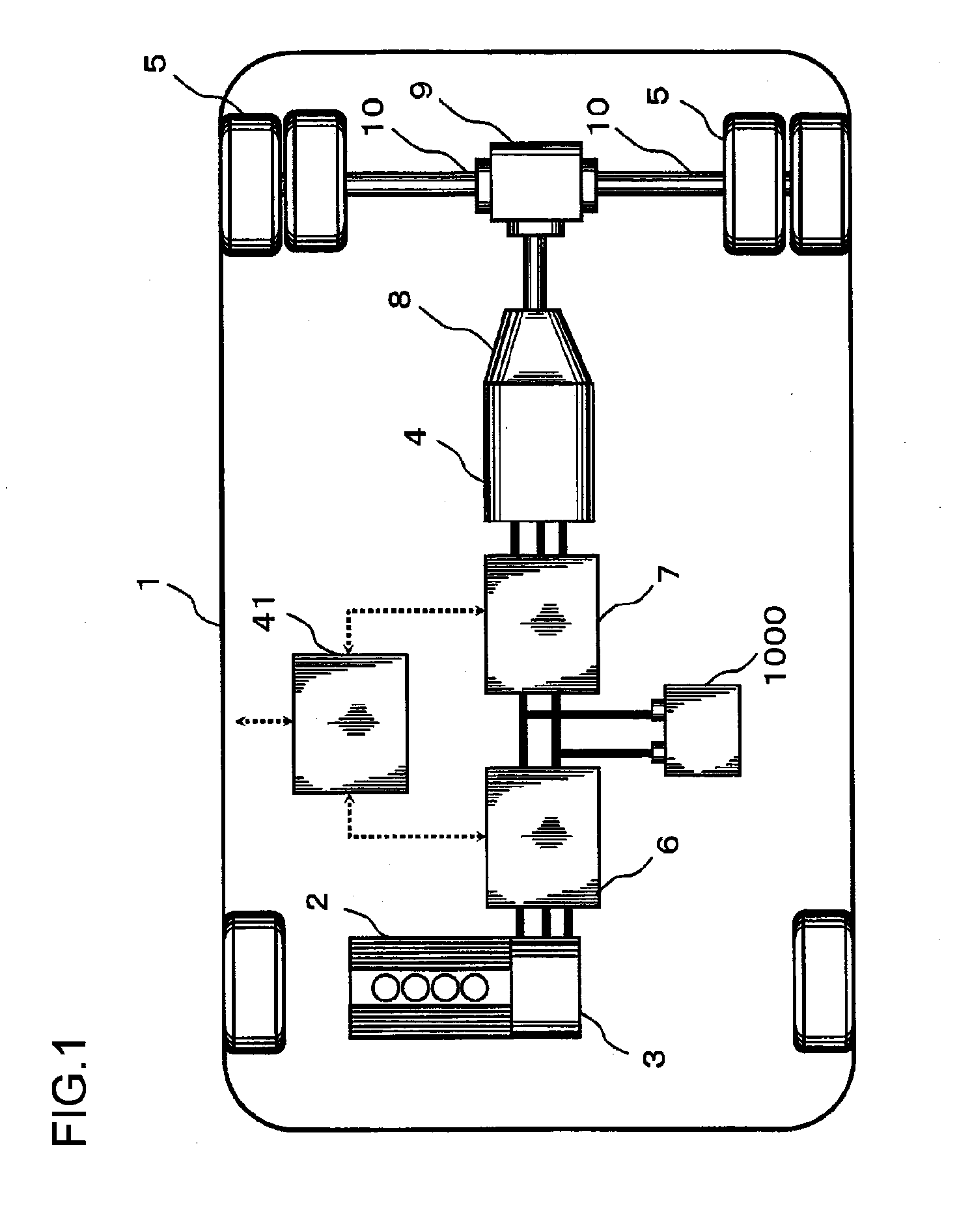
[0026]FIG. 1 shows the general layout of a drive system for a large sized electric hybrid vehicle. The drive system of the hybrid vehicle 1 of this embodiment is constructed according to the so called series hybrid principle, in which energy flows in series from an engine 2 to drive wheels 5: a motor-generator 3 (here this...


PUM


Abstract

A plurality of resistance value tables of a battery group with respect to temperature and SOC of the assembled battery, which are measured in advance when currents of different change patterns flow in the assembled battery, are stored. A resistance value for the assembled battery is calculated, based upon its voltage and current. From among the plurality of resistance value tables, a resistance value table is selected so that it corresponds to the change pattern of the current flowing in the assembled battery when the voltage and the current of the assembled battery were measured, and a resistance value is searched for from that resistance value table corresponding to the temperature and the SOC of the assembled battery. Then the calculated resistance value and the one from the table are compared to determine the life of the assembled battery.

Description

INCORPORATION BY REFERENCE[0001]The disclosure of the following priority application is herein incorporated by reference: Japanese Patent Application No. 2009-004724 filed Jan. 13, 2009.BACKGROUND OF THE INVENTION[0002]1. Field of the Invention[0003]The present invention relates to a control device for a battery.[0004]2. Description of the Related Art[0005]In the prior art, with a hybrid vehicle (HEV: hybrid electric vehicle) in which both an internal combustion engine and an electric motor are used together, or with an electric automobile (PEV: plug-in electric vehicle) that travels using only an electric motor, a battery assembly is used as the power supply for the electric motor, in which a plurality of battery modules, such as for example secondary lithium ion batteries or the like, are connected in series and series-parallel. Consideration is given by a charge / discharge control device for these secondary lithium ion batteries to the amount of charge of each of the battery cells...

Claims


Application Information

Patent Timeline
IPC IPC(8): G01R31/36G06F19/00B60L3/00H01M10/42H01M10/44H01M10/48H02J7/00
CPCB60L3/0046B60L50/64B60L2210/40B60L2240/545B60L2240/547B60L2240/549B60L2270/20H01M10/482H01M10/486Y02T10/6217Y02T10/7011Y02T10/7016Y02T10/7044Y02T10/7061Y02T10/7077Y02T10/7241G01R31/3842G01R31/367G01R31/396G01R31/389B60L50/61B60L50/16B60L58/18B60L58/12B60L58/22B60L2210/30B60L58/16Y02T10/62Y02T10/70Y02T10/72Y02T10/7072Y02E60/10
Inventor AOSHIMA, YOSHINORIUEDA, MASAHIROKAWAHARA, YOUHEIHIGASHIMOTO, KOUJI
Owner HITACHI VEHICLE ENERGY
Why Eureka
Try Eureka