Sensor device and method for manufacturing a sensor device

a sensor device and sensor technology, applied in the direction of turn-sensitive devices, acceleration measurement using interia forces, instruments, etc., to achieve the effect of reducing the kinetic energy released in the case of overload

Active Publication Date: 2010-07-29
ROBERT BOSCH GMBH
View PDF1 Cites 40 Cited by
  • Summary
  • Abstract
  • Description
  • Claims
  • Application Information

AI Technical Summary

Benefits of technology

[0011]According to example embodiments of the present invention, via the resilient construction of the at least one raised stop relative to the displaceable remaining area of the seismic mass, the kinetic energy released upon collision with the at least one stop can be converted into bending energy for a reversible bending of the at least one spring. In this manner, the kinetic en...

Problems solved by technology

However, this creates the risk that when there is a significant acceleration in direct...

Method used


Image

  • Sensor device and method for manufacturing a sensor device
  • Sensor device and method for manufacturing a sensor device
  • Sensor device and method for manufacturing a sensor device

Examples


Embodiment Construction

[0033]FIG. 2 shows a top view of a lower side of a seismic mass of a sensor device according to an example embodiment of the present invention.

[0034]Seismic mass 50, fashioned as a rocker, is fastened to a base plate of the sensor device via flexible springs 52 and an anchor 54. The base plate can be a subunit of a housing of the sensor device. However, it should be appreciated that the subject matter hereof is not limited to a seismic mass 50 situated in an airtight housing.

[0035]Flexible springs 52 and anchor 54 can be fashioned in one piece with seismic mass 50. For example, at least the four flexible springs 52, anchor 54, and seismic mass 50 are structured out from a single micromechanical functional layer. However, here it is to be noted that the sensor device described here is not limited to a particular number or configuration of flexible springs 52 and / or of the at least one anchor 54.

[0036]Between anchor 54 and the base plate, it is possible to additionally situate at leas...


PUM

PropertyMeasurementUnit
Accelerationaaaaaaaaaa
Areaaaaaaaaaaa
Distributionaaaaaaaaaa

Abstract

A sensor device includes a base plate, a seismic mass having an upper side and a lower side that is situated such that given acceleration of the base plate the seismic mass is capable of being displaced in a direction oriented non-parallel to the upper side and/or to the lower side, at least one raised stop on the seismic mass, and a detection and evaluation device that is adapted to acquire a displacement movement of the seismic mass relative to the base plate and, taking into account the displacement movement, to determine an item of information relating to an acceleration of the sensor device and/or to a force acting on the sensor device, the seismic mass having at least one resilient area that includes the at least one stop and at least one displaceable remaining area, and the resilient area being connected to the remaining area via at least one spring. A method is for manufacturing a sensor device.

Description

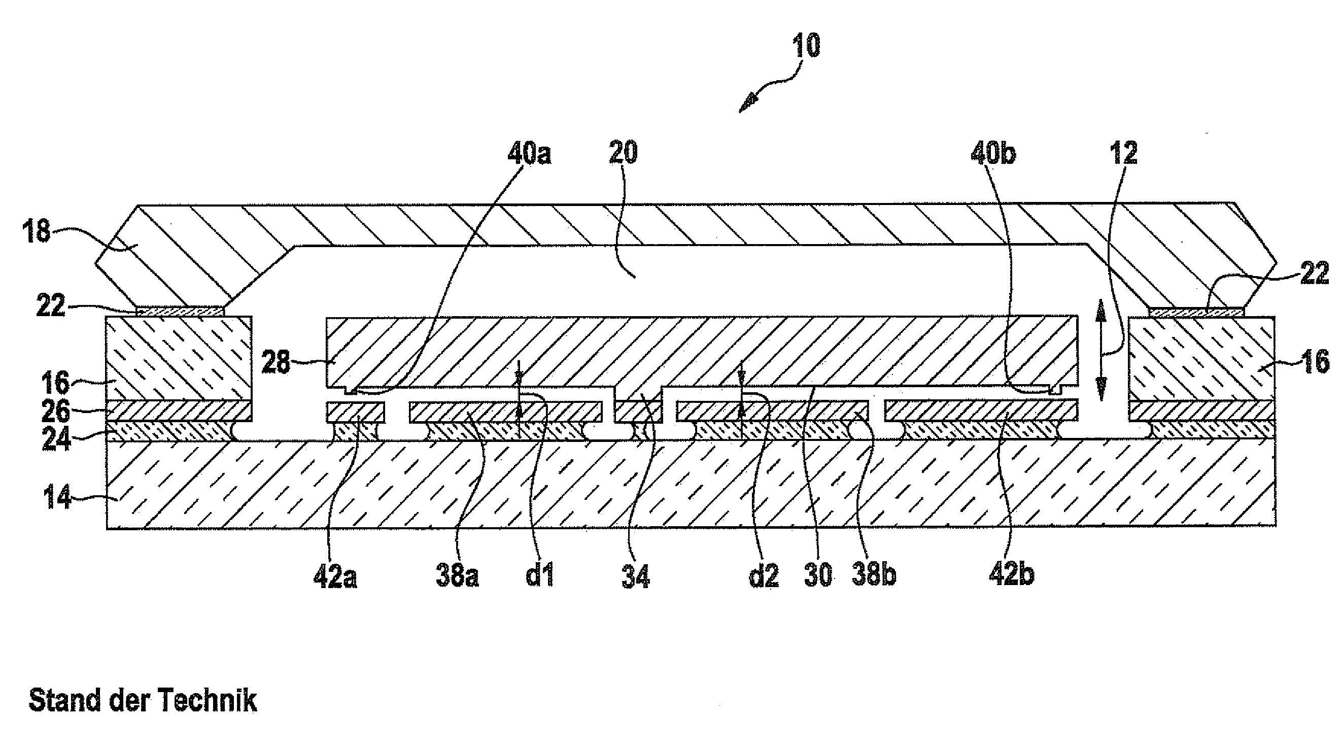
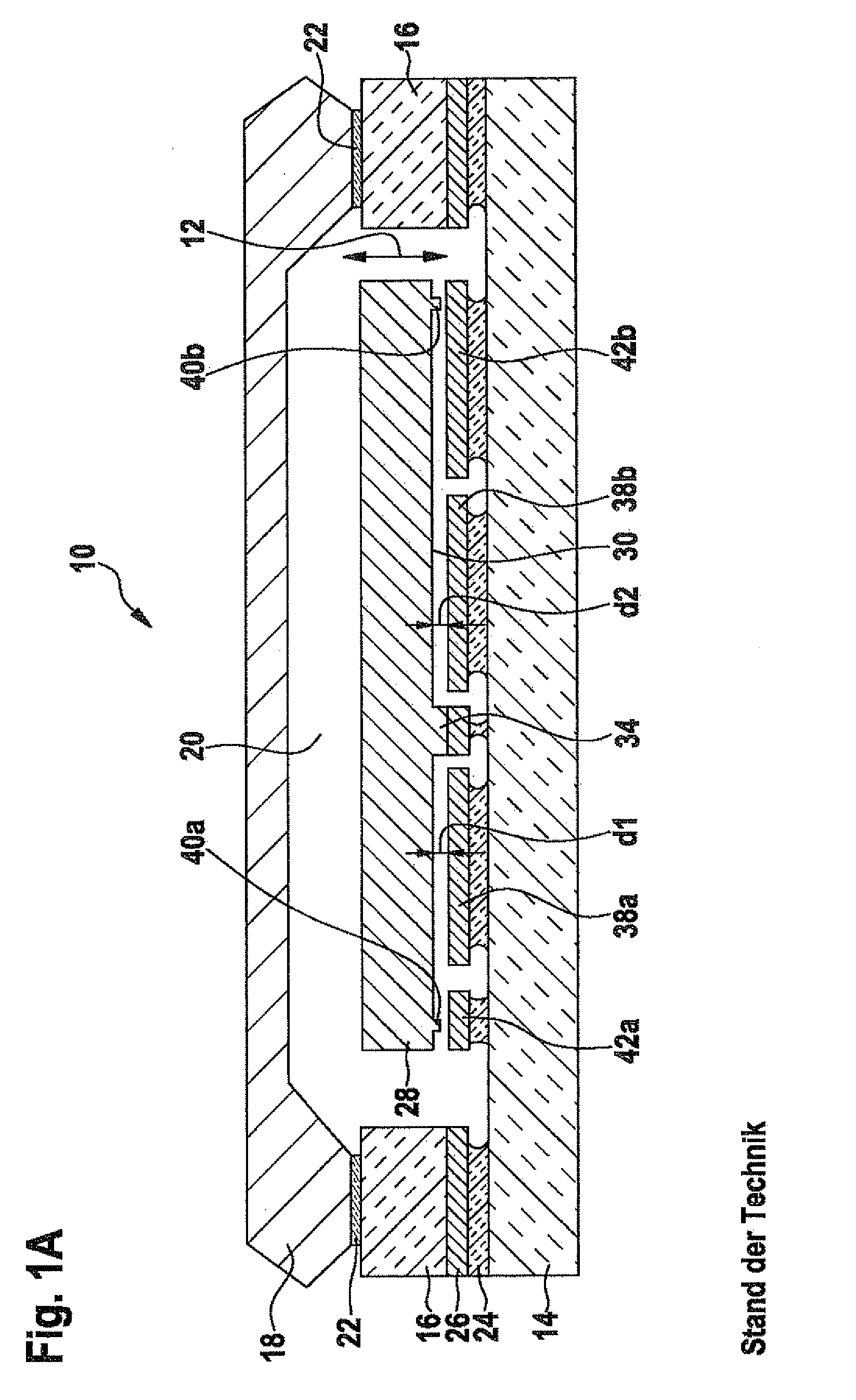
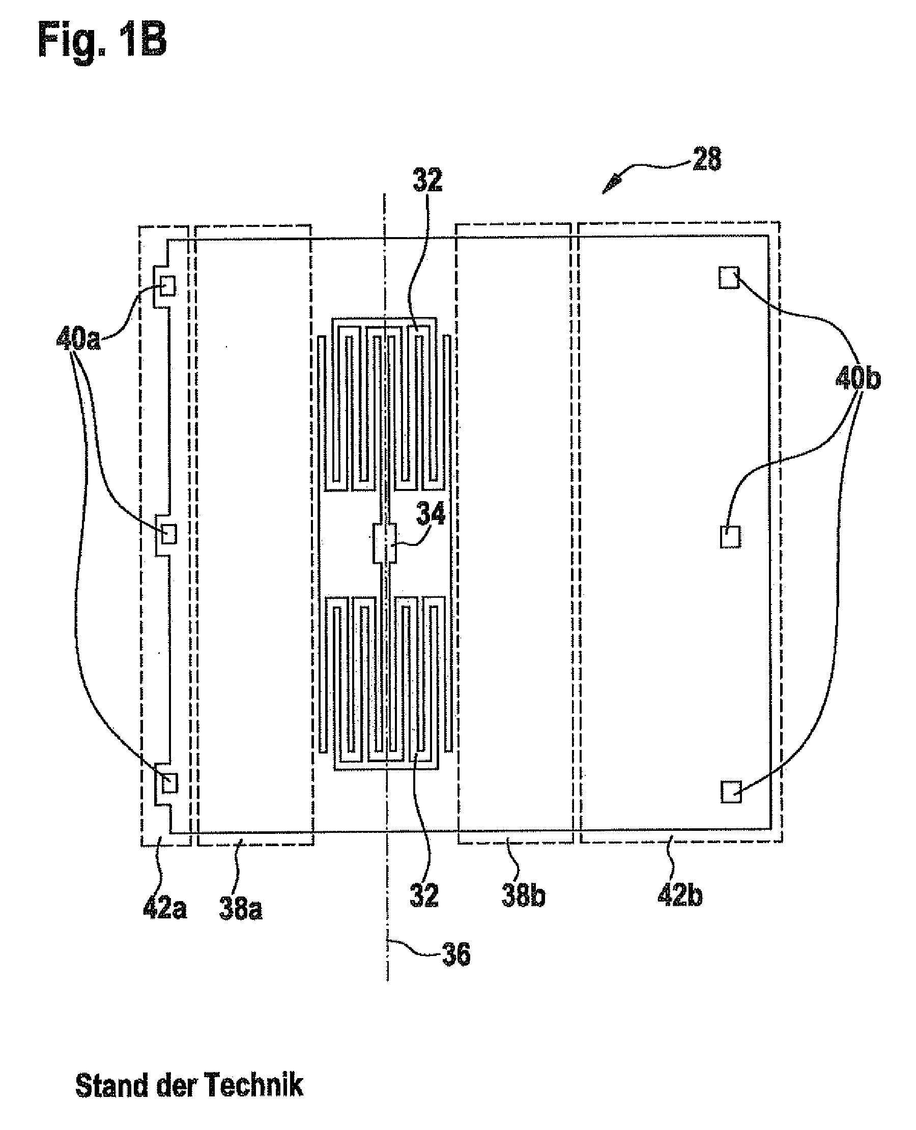
CROSS-REFERENCE TO RELATED APPLICATION[0001]The present application claims priority to Application No. 10 2009 000 407.6, filed in the Federal Republic of Germany on Jan. 26, 2009, which is expressly incorporated herein in its entirety by reference thereto.FIELD OF THE INVENTION[0002]The present invention relates to a sensor device and to a method for manufacturing such a sensor device.BACKGROUND INFORMATION[0003]In order to determine a rotational acceleration and / or a linear acceleration acting on a movable body, an inertial sensor is often attached to the movable body.[0004]FIGS. 1A and 1B show a cross-section and a top view representing a conventional inertial sensor.[0005]The schematically shown inertial sensor, as acceleration sensor 10, is fashioned in order to determine a linear acceleration, oriented in a direction 12 perpendicular to a substrate 14, of acceleration sensor 10, and to define a quantity corresponding to the acceleration. Substrate 14 forms, together with a fra...

Claims


Application Information

Patent Timeline
IPC IPC(8): G01C19/56H01L21/50
CPCG01C25/00G01P15/125Y10T29/49002G01P2015/0831
Inventor GUENTHER, SEBASTIANKAACK, ROLF
Owner ROBERT BOSCH GMBH
Why Eureka
Try Eureka