Exhaust valve mechanism for an internal combustion engine

a technology of exhaust valve and internal combustion engine, which is applied in the direction of valve arrangement, machine/engine, output power, etc., can solve the problems of high cost, more vulnerable to mechanical systems, and low exhaust temperature for exhaust after treatment system, so as to shorten the expansion stroke. the effect of the expansion stroke and the increase of the exhaust temperatur

Active Publication Date: 2010-07-29
VOLVO LASTVAGNAR AB
View PDF4 Cites 23 Cited by
  • Summary
  • Abstract
  • Description
  • Claims
  • Application Information

AI Technical Summary

Benefits of technology

[0003]One way to modify the thermodynamic process of the engine during low load operation in order to increase the exhaust temperature is to shorten the duration of the expansion stroke. A shortened expansion stroke will result in less torque to crankshaft and energy remainin

Problems solved by technology

When a heavy duty Diesel engine is operated under low load and/or idling, the exhaust temperature is low or even far too low for an Exhaust After Treatment System (EATS) comprising a catalyst to function properly.
However, these systems rely on e

Method used


Image

  • Exhaust valve mechanism for an internal combustion engine
  • Exhaust valve mechanism for an internal combustion engine
  • Exhaust valve mechanism for an internal combustion engine

Examples


Embodiment Construction

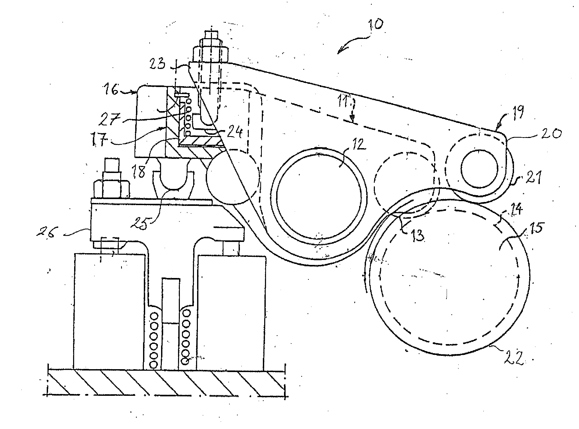
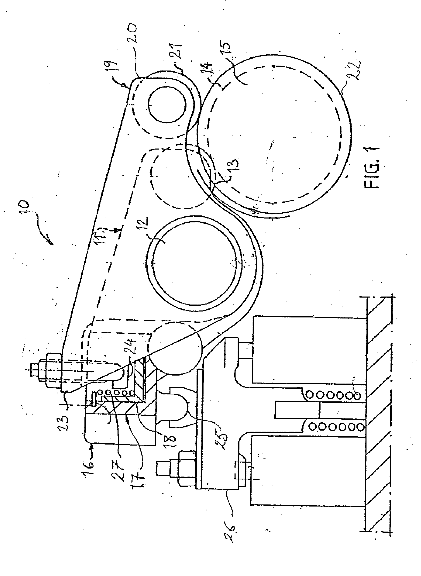
[0014]FIG. 1 schematically illustrates a prior art valve mechanism 10 as described in U.S. Pat. No. 6,983,725 for use in an internal combustion engine (not shown). The mechanism 10 comprises a main exhaust valve rocker arm 11, which is rockably mounted on a rocker arm shaft 12. One end of the main rocker arm 11 has a cam follower roller 13, rotatably mounted thereon. The cam follower roller 13 is in contact with a schematically shown cam element 14 on the camshaft 15. At its end 16 opposite to the end with the cam follower roller 13, the main rocker arm 11 is provided with a piston cylinder arrangement 17 comprising a master piston 18 and a slave piston 25 located in two corresponding piston cylinders in the main rocker arm end 16.

[0015]A secondary rocker arm 19 is arranged beside the main rocker arm and mounted on the rocker arm shaft 12 for activation of an exhaust brake mode. One end 20 of the secondary rocker arm 19 has a cam follower roller 21, rotatably mounted thereon. The ca...


PUM


Abstract

In an exhaust valve mechanism for an internal combustion engine the main rocker arm is mounted on a rocker arm shaft for normal valve operation via a cam element. A secondary rocker arm is mounted on the shaft for activation of an exhaust brake mode. The activation is achieved through supply of hydraulic pressure to a piston cylinder arrangement acting between the main and secondary rocker arms. A master piston and a slave piston are connected by a hydraulic-link allowing activation by increased hydraulic pressure. When activating the exhaust gas temperature increasing mode, the master piston is moved to an active position for part of its stroke against the force of a first resilient member. When activating the exhaust brake mode, the master piston is moved the full movement of its stroke against the combined forces of the first resilient member and a second resilient member as active position. The end of the first stroke length defines a position for the master piston allowing activation of an extra valve event.

Description

BACKGROUND AND SUMMARY[0001]The invention relates to an exhaust valve mechanism for an internal combustion engine.[0002]When a heavy duty Diesel engine is operated under low load and / or idling, the exhaust temperature is low or even far too low for an Exhaust After Treatment System (EATS) comprising a catalyst to function properly. At low engine speeds, it is typically necessary to provide an auxiliary burner in the post-turbine exhaust. Such a solution involves the use of additional fuel.[0003]One way to modify the thermodynamic process of the engine during low load operation in order to increase the exhaust temperature is to shorten the duration of the expansion stroke. A shortened expansion stroke will result in less torque to crankshaft and energy remaining in the exhaust gas expressed as higher temperature. This elevated exhaust temperature is very beneficial for the function of EATS. The reduced torque delivered to the crankshaft has to be compensated by increased fuelling, wh...

Claims


Application Information

Patent Timeline
IPC IPC(8): F02D13/04F01L1/34F01L1/18
CPCF01L1/181F01L1/2411F01L1/26F01L13/06F01L2001/186F01L2013/0089F01L2820/02F02D13/0242F02D13/04
Inventor PERSSON, PEROLSSON, GORAN
Owner VOLVO LASTVAGNAR AB
Why Eureka
Try Eureka