Closed electron drift thruster

Active Publication Date: 2010-07-29
SN DETUDE & DE CONSTR DE MOTEURS DAVIATION S N E C M A
View PDF6 Cites 5 Cited by
  • Summary
  • Abstract
  • Description
  • Claims
  • Application Information

AI Technical Summary

Benefits of technology

[0024]Nevertheless, given the measures recommended by the invention, it is also possible to obtain excellent results with t

Problems solved by technology

Nevertheless, for space missions that require high power and high specific impulse, closed electron drift plasma thrusters present drawbacks in thermal terms since the outer annular coil involves a long length of wire which gives rise to a high level of heat dissipation and to a winding that is of mass that is likewise high.
Nevertheless, it has been found that the radial magnetic field delivered by the multiple outer coil thrusters is not rigorously uniform, with variations that m

Method used


Image

  • Closed electron drift thruster
  • Closed electron drift thruster
  • Closed electron drift thruster

Examples


Embodiment Construction

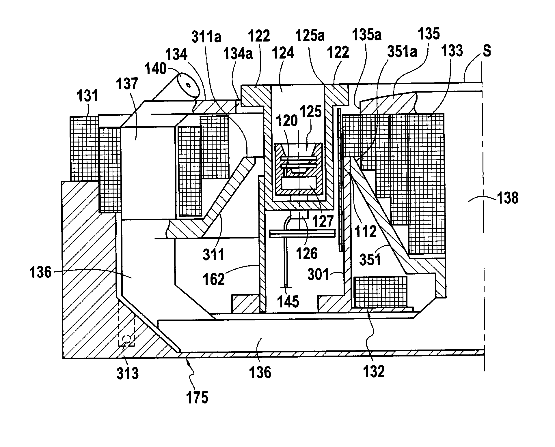
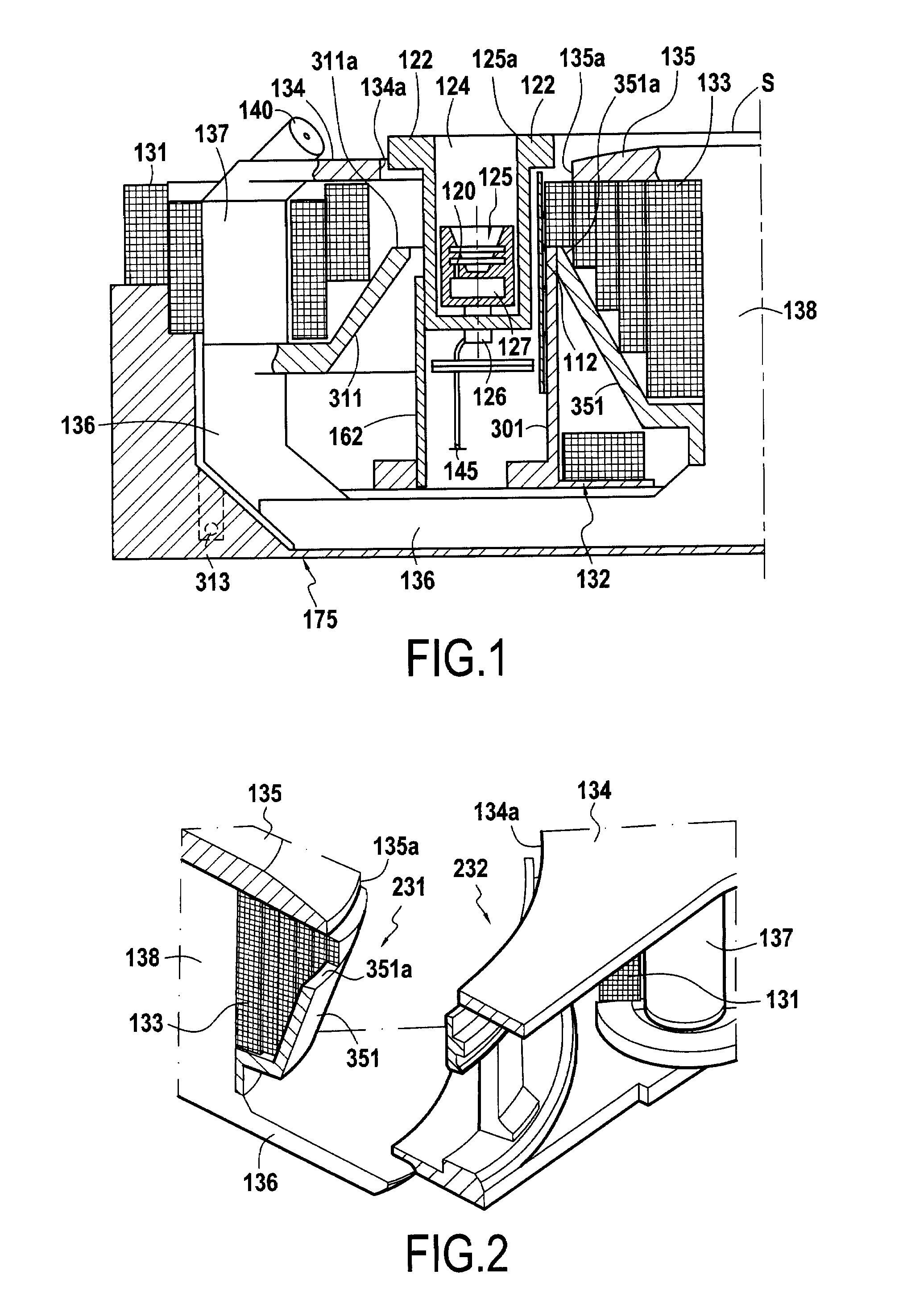
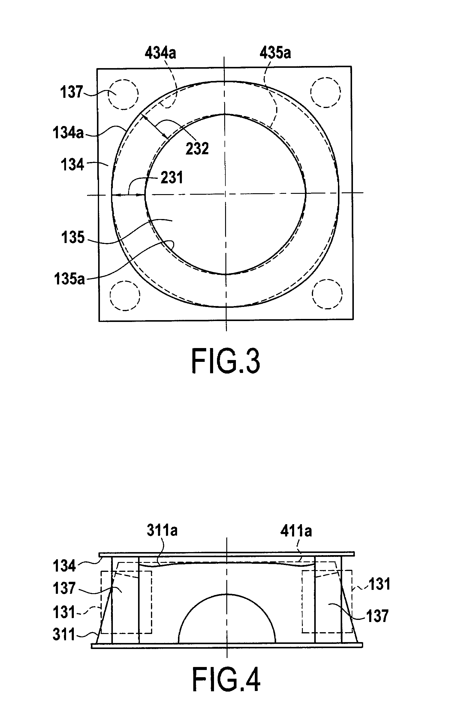
[0034]FIGS. 1 to 4 show a first embodiment of a closed electron drift thruster to which the present invention applies.

[0035]A thruster of this type comprises a basic structure that corresponds to a large extent to the description that is given in patent document EP 0 982 976.

[0036]The plasma thruster thus essentially comprises a main annular ionization and acceleration channel 124 defined by insulating walls 122. The channel 124 is open at its downstream end 125a and in an axial plane it presents a section of frustoconical shape in its upstream portion, and of cylindrical shape in its downstream portion. A hollow cathode 140 is placed outside the main channel 124 and an annular anode 125 is placed in the main channel 124. An ionizable gas manifold 127 fed by a pipe 126 serves to inject ionizable gas through holes 120 formed in the wall of the anode 125. A wire 145 for biasing the anode 125 can also be seen in FIG. 1.

[0037]Discharge between the anode 125 and the cathode 140 is contro...


PUM


Abstract

In a closed electron drift thruster, a magnetic circuit for creating a magnetic field in a main annular channel comprises at least one axial magnetic core surrounded by a first coil and an inner upstream pole piece forming a body of revolution, together with a plurality of outer magnetic cores surrounded by outer coils. The magnetic circuit further comprises an essentially radial outer first pole piece defining a concave inner peripheral surface and an essentially radial second pole piece defining a convex outer peripheral surface. The concave inner peripheral surface and the convex outer peripheral surface present respective adjusted profiles that are distinct from circular cylindrical surfaces so as to form between them a gap of varying width presenting zones of maximum value in register with the outer coils and zones of minimum value in between the outer coils so as to create a uniform radial magnetic field.

Description

FIELD OF THE INVENTION [0001]The present invention relates to a closed electron drift thruster comprising a main annular ionization and acceleration channel about an axis of the thruster, at least one hollow cathode, an annular anode concentric about the main annular channel, a pipe and a manifold for feeding the anode with ionizable gas, and a magnetic circuit for creating a magnetic field in said main annular channel, said magnetic circuit comprising at least one axial magnetic core surrounded by a first coil and by an inner upstream pole piece forming a body of revolution, and a plurality of outer magnetic cores surrounded by outer coils.PRIOR ART[0002]Various types of closed electron drift thruster are already known.[0003]A first type of closed electron drift thruster includes an outer pole piece that is magnetized by an annular coil.[0004]A thruster of that type with a shielded outer coil is described for example in document EP 0 900 196 A1.[0005]Patent document FR 2 693 770 A1...

Claims


Application Information

Patent Timeline
IPC IPC(8): H05H1/54H01J27/14F03H1/00
CPCF03H1/0075
Inventor DUCHEMIN, OLIVIERVALENTIAN, DOMINIQUE
Owner SN DETUDE & DE CONSTR DE MOTEURS DAVIATION S N E C M A
Why Eureka
Try Eureka