Low power drive circuit

a driver circuit and low power technology, applied in the direction of light sources, instruments, lighting devices, etc., can solve the problem that the light emitter typically consumes a significant part of the power requirement of the optical interconnect, and achieve the effect of low power consumption, fast response time and easy integration

Active Publication Date: 2010-07-29
NVIDIA DENMARK APS
View PDF7 Cites 0 Cited by
  • Summary
  • Abstract
  • Description
  • Claims
  • Application Information

AI Technical Summary

Benefits of technology

[0030]In principle the light emitter may be any suitable type for sending signals via the light carrier of the system, such as an optical fiber or a planar waveguide. It is often preferable that the light emitter has one or more of a low power consumption, a fast response time, easy integration and a low cost. In one embodiment light emitter is selected from the group of VCSEL, a photodiode, a laser, a laser diode and a Mach-Zender modulator.

Problems solved by technology

In such a setup the light emitter typically consumes a significant part of the power requirement of the optical interconnect.
Increasing the current driven through the emitter from zero to above said threshold may be time consuming, and therefore a bias current is typically driven through the light source.

Method used


Image

  • Low power drive circuit
  • Low power drive circuit
  • Low power drive circuit

Examples


Embodiment Construction

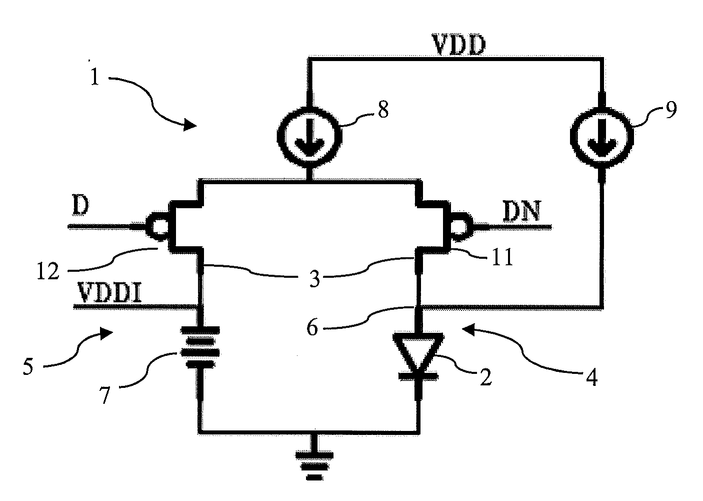
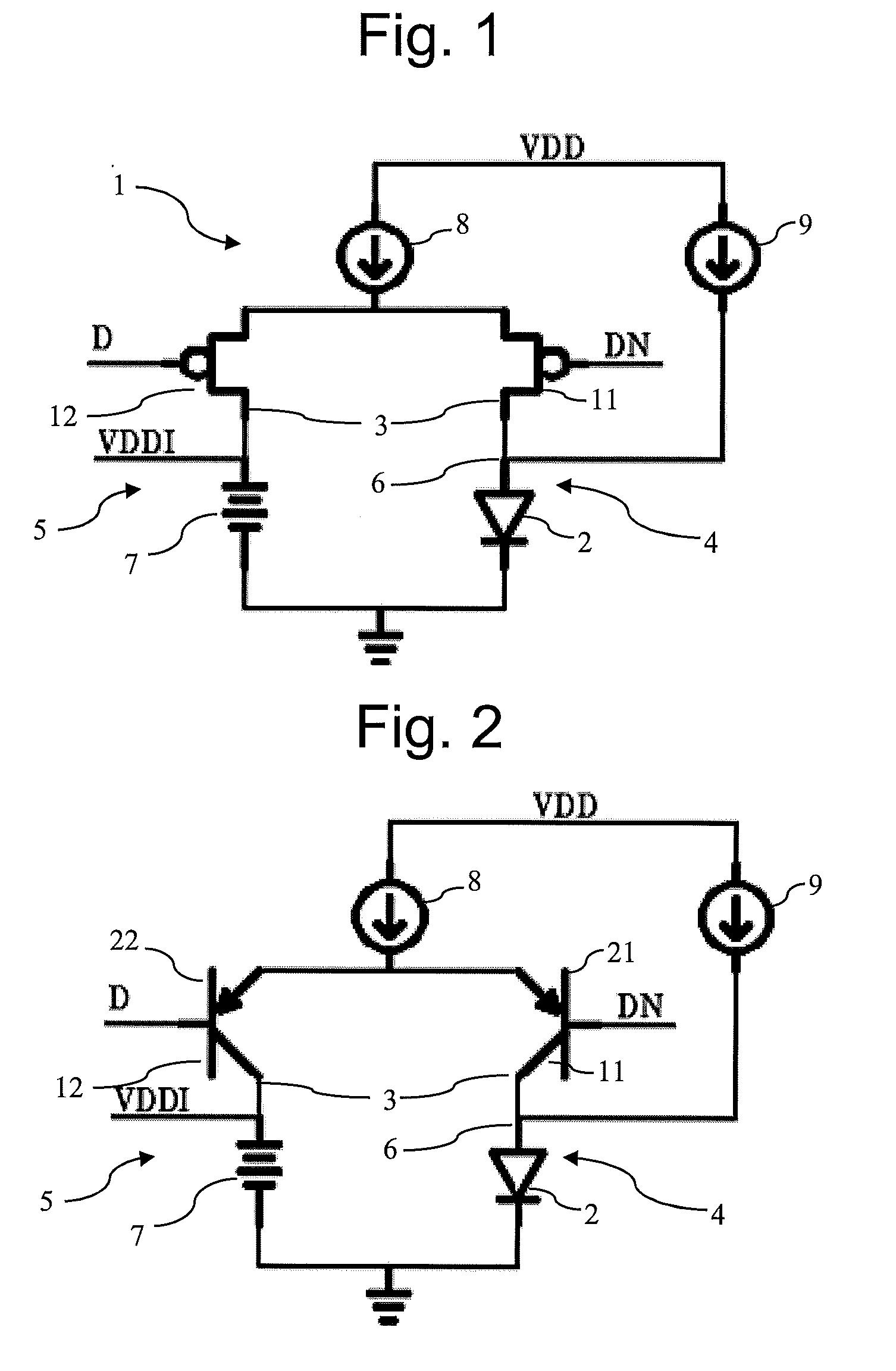
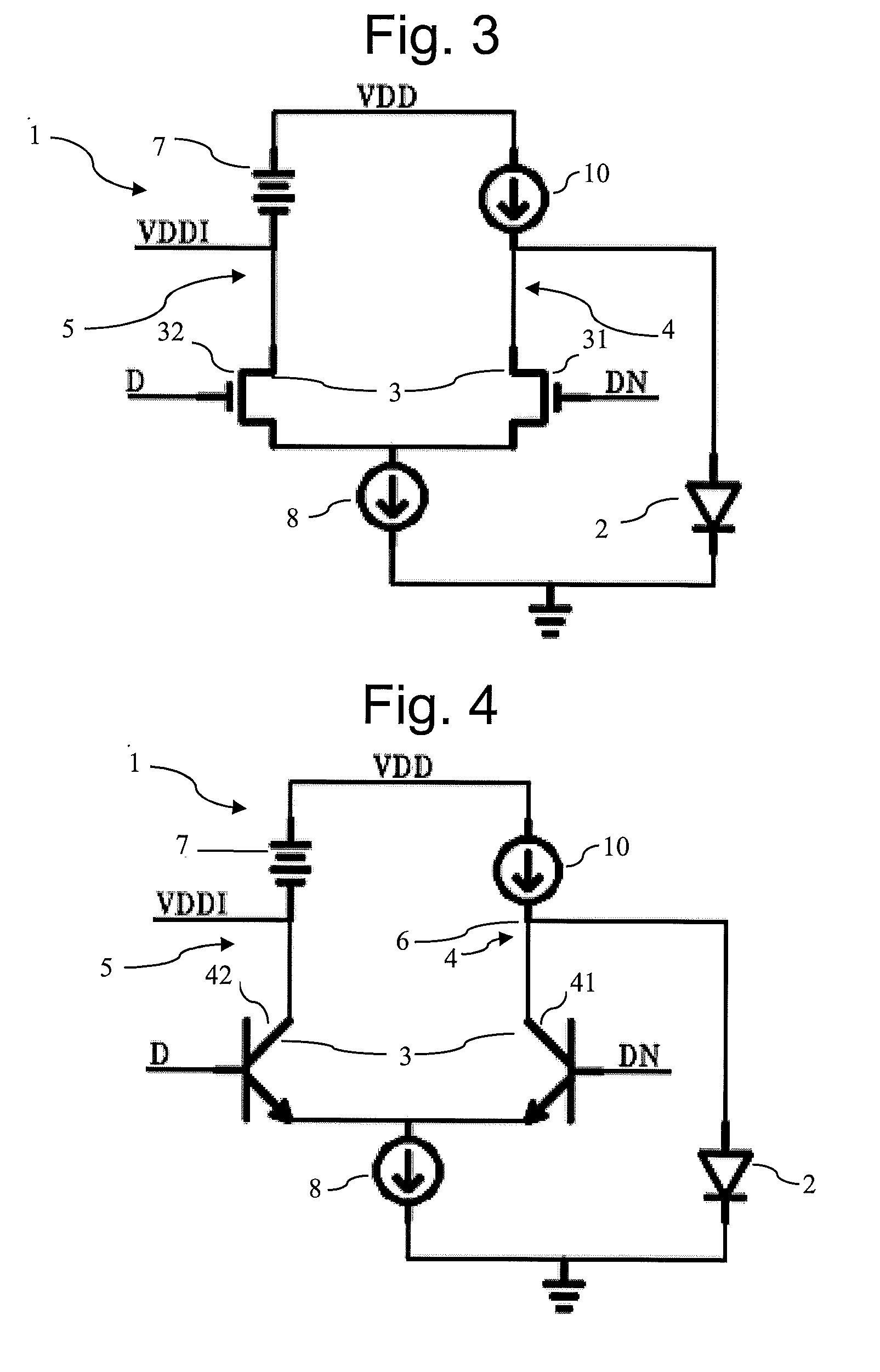
[0016]As explained above a driver circuit often provides the variation of the signal current, i.e. current driven through the light emitter, by shifting the flow of current from a set of current sources. Such current sources are often adjustable or programmable to allow the driver circuit design to be applied to different applications and / or to drive different light emitters. In one embodiment at least one of the current sources of the driver circuit is programmable, such as programmable by switching on a desired number of current sub-sources. In one embodiment at least one current source is programmable to allow compensation of effects induced by environmental factors and / or aging of the circuit and / or the light emitter.

[0017]In one embodiment, the driver circuit is arranged to provide a signal current by combining currents from two current sources. In such one embodiment one source provides an offset current IOFFSET, referred to as an offset current source, whereas the other provi...


PUM


Abstract

The invention relates to an integrated driver circuit suitable for driving a light emitter with a signal current I(time) based on a received signal said circuit comprising a differential pair of transistors having a first transistor and a second transistor each respectively forming part of a first branch and a second branch, said first branch comprises a node suitable for connecting to said light emitter and/or said first branch comprises said light emitter, wherein said second branch comprise at least one charge storage device. This charge storage device may be arranged to collect current otherwise wasted in the process of driving the light emitter. This current may be utilized to drive circuitry thereby reduce current consumption.

Description

TECHNICAL FIELD[0001]The present invention relates to an integrated driver circuit suitable for driving a light emitter with a modulated current I(time) said circuit comprising a differential pair of transistors having a first transistor and a second transistor each respectfully forming part of a first branch and a second branch, said first branch comprises a node suitable for connecting to said light emitter and / or said first branch comprises said light emitter. The invention further relates to a chip and system each comprising such an integrated driver circuit.BACKGROUND[0002]The demands for ever-increasing bandwidths in digital data communication equipment at reduced power consumption levels are constantly growing. These demands not only require more efficient integrated-circuit components, but also high performance interconnect structures and devices. Indeed, as one example, the International Technology Roadmap for Semiconductors (ITRS) projects that high performance chips in th...

Claims


Application Information

Patent Timeline
Patent Type & Authority Applications(United States)
IPC IPC(8): H05B37/02
CPCH05B33/0815H05B45/30
Inventor MORTENSEN, ANDERS S.KEIL, ULRICH
Owner NVIDIA DENMARK APS
Why Eureka
Try Eureka