
Method and means for improving combustion efficiency

Inactive Publication Date: 2010-07-29
EPELBAUM SHAUL S +1
View PDF9 Cites 9 Cited by
  • Summary
  • Abstract
  • Description
  • Claims
  • Application Information

AI Technical Summary

Benefits of technology

[0012]More complete and efficient combustion of a viscous heavy fuel oil in a boiler or other combustion device is obtained by heating a feed stream of oil supplied to the boiler to a temperature at which its viscosity is lowered sufficiently to obtain efficient atomization, and mixing an effective amount of a high molecular weight, long chain, viscoelastic polymer to the heated oil through carefully controlled mechanical mixing at conditions that avoid degradation of the polymer at a location just before introduction of the oil into the combustion device.

Problems solved by technology

It is well known that the addition of a low concentration of a long chain, high molecular weight, hydrocarbon polymer to a liquid hydrocarbon can result in significant changes to the flow behavior of the resulting solution.
Those attempts have met with failure in that no measurable increase in combustion efficiency could be observed.

Method used


Image

  • Method and means for improving combustion efficiency
  • Method and means for improving combustion efficiency

Examples


example 1

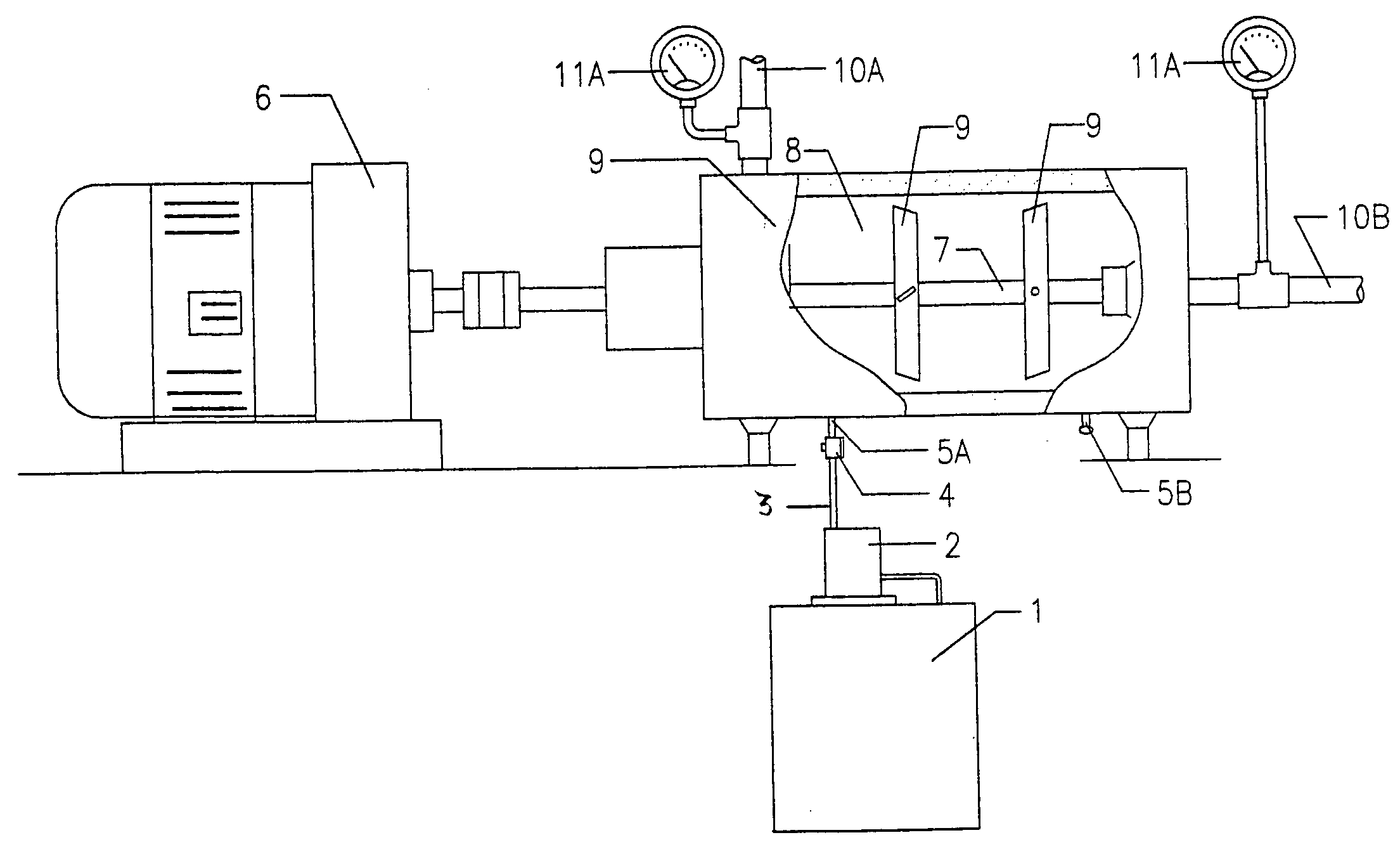
[0028]A mixing device was constructed generally in accordance with that illustrated in the Figure for use in a field test of the system. The internal diameter of the mixing chamber was 3 inches and its length was 12 inches, thus providing a chamber volume of approximately 85 cubic inches. The device had three sets of mixing blades, each set being 2 inches in diameter.

[0029]The test was conducted at a textile plant that had two identical 200 HP boilers burning No. 6 Residual fuel oil. Fuel was supplied to the two boilers from a single, heated, 1000 gallon day tank that was arranged to measure fuel usage, and to supply either one, or both, of the two boilers. Steam generated by each of the boilers was fed to a common accumulator. The described mixing device was installed in the fuel line of a first of the boilers at a location after the day tank but before the boiler while the fuel line of the second boiler ran directly from the day tank to the boiler.

[0030]Historical data gathered ov...

example 2

[0033]This test employed a diesel-electric generator burning No. 6 Residual fuel oil to produce electricity for an industrial plant. The same mixing apparatus and the same polymer additive used in Example 1 were employed in this test. A fuel oil stream heated to a temperature of 120° C. was continuously fed into the mixing apparatus along with a stream of the polymer additive. The polymer additive was fed into the mixing apparatus at a rate of 1 ounce per 30 gallons of fuel oil to give a polymer concentration in the fuel oil stream exiting the mixing apparatus of approximately 5 ppm, and the residence time of the fuel oil in the mixing apparatus was approximately 7 seconds. An 18.6% reduction in fuel consumption per kilowatt hour of electricity produced was observed when the diesel-electric generator operated with the additive-treated fuel oil.

[0034]Although the Example was directed specifically to a fuel additive comprising a solution of polyisobutylene, other substantially linear ...


PUM

PropertyMeasurementUnit
Temperatureaaaaaaaaaa
Fractionaaaaaaaaaa

Abstract

A more complete combustion and a decrease in particulate emissions in the burning of a heavy fuel oil in an industrial boiler or similar combustion device is obtained by first heating the oil to a temperature sufficient to significantly lower its viscosity and continuously mixing a fuel additive containing a solution of a high molecular weight, substantially linear, viscoelastic polymer to the heated oil flowing to the combustion device by mechanically stirring the oil and additive at conditions that do not cause degradation of the viscoelastic polymer through rupture and breakage of polymer molecules.

Description

BACKGROUND OF THE INVENTION[0001]1. Technical Field[0002]This invention relates generally to a method for improving the efficiency obtained in the burning of a heavy fuel oil in a boiler or other combustion device and to methods and means for preparing the fuel oil for combustion.[0003]More specifically, this invention relates to a method for improving the combustion efficiency of a heavy fuel oil by mixing an effective amount of a combustion enhancing material comprising a high molecular weight, viscoelastic polymer to a heated fuel oil just prior to its combustion.[0004]This invention further relates to a means for producing a homogeneous mixture of a heavy fuel oil and a viscoelastic polymer without degradation of the polymer or interfering with normal operations of the combustion device[0005]2. Description of Related Art[0006]It is well known that the addition of a low concentration of a long chain, high molecular weight, hydrocarbon polymer to a liquid hydrocarbon can result in...

Claims


Application Information

Patent Timeline
IPC IPC(8): F23D11/44
CPCB01F3/0853B01F3/2078B01F7/04C10L1/16C10L1/1616F23K5/20C10L10/00C10L10/02F23K5/10F23K5/14C10L1/1641B01F23/43B01F23/711B01F27/70
Inventor EPELBAUM, SHAUL S.TRIPPE, JERRY C.
Owner EPELBAUM SHAUL S
Learn More