

Sers-active structure for use in raman spectroscopy
a technology of active structures and raman, which is applied in the field of surface enhanced raman spectroscopy, can solve problems such as difficult reproduction and unsuitability for high-volume production
- Summary
- Abstract
- Description
- Claims
- Application Information
AI Technical Summary
Benefits of technology
Problems solved by technology
Method used
Image

Examples
Embodiment Construction
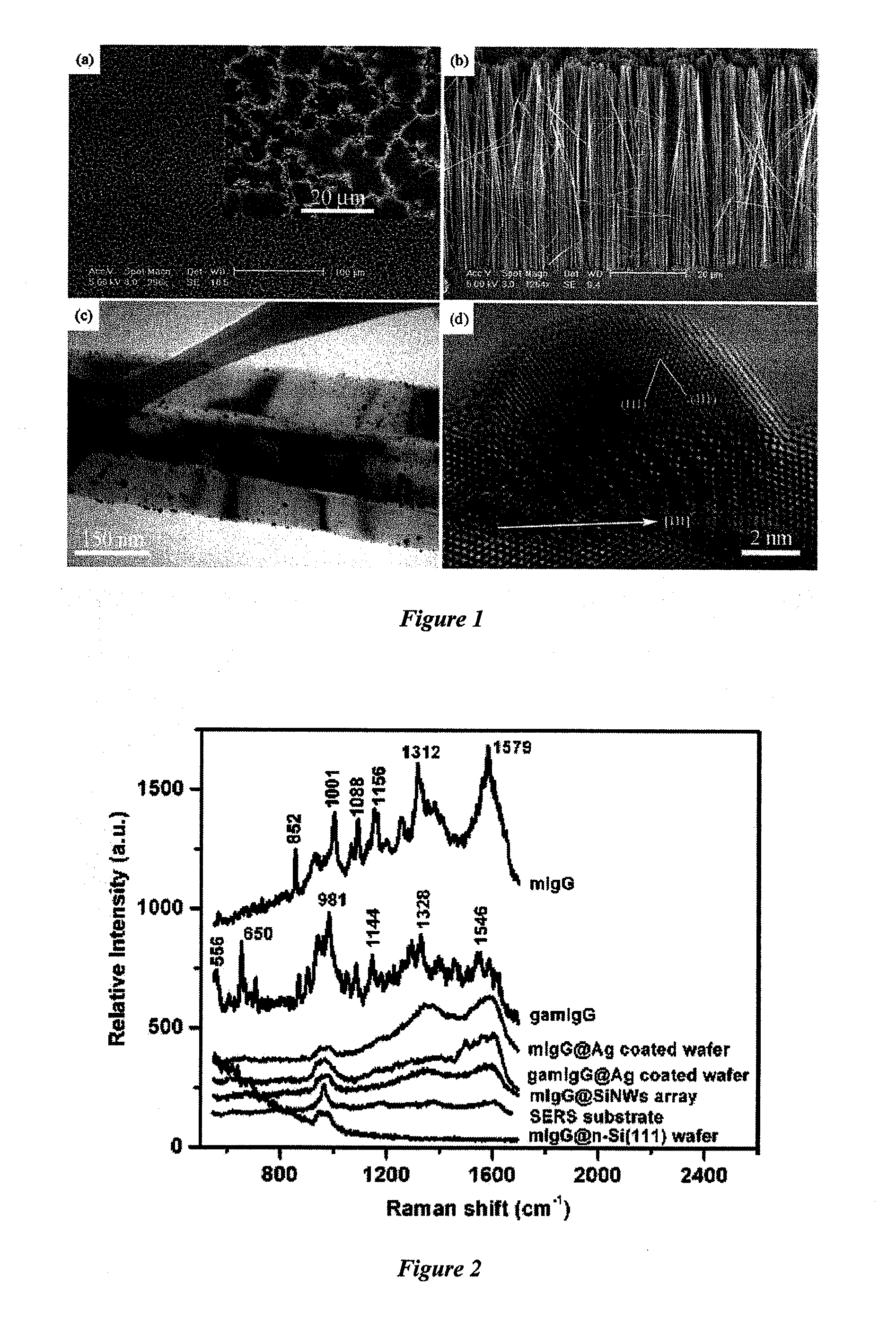
[0010]The present invention will be described in detail with reference to the drawings. The described embodiment consists of a silicon (Si) substrate with an array of Si nanowires formed on the substrate and coated with silver (Ag) nanoparticles. This is not however meant to limited the scope of the invention and the skilled addressee will appreciates that other materials may be used for the substrate, nanowires and nanoparticles including, but not limited to:[0011]for the substrate: semiconductors groups IV, II-VI, III-V and their complex compounds, carbon, diamond, Si, Ge, ZnO, ZnS, ZnSe, CdS, CdSe, BN, AlN, GaN, InP, GaAs SiC,[0012]for the nanoarray of nanostructures: as for the substrate as well as inorganic and organic semiconductors, conductors, insulators, molecules, polymer and bio-molecules, and[0013]for the nanoparticles: Au, Ag, Cu, Fe, Co, Ni, Ru, Rh, Pd, Pt or their composites.
[0014]A preferred embodiment of a surface-enhanced Raman spectroscopy (SERS)—active substrate ...
PUM
 Abstract
Description
Claims
Application Information