

Subretinal access device
a subretinal access and device technology, applied in the field of eye surgery instruments, can solve the problems of reducing visual acuity, eventually blindness, and difficult to perform interventional procedures targeting tissues beneath the sensory retina, and achieve the effect of stabilizing the device location and facilitating imaging
- Summary
- Abstract
- Description
- Claims
- Application Information
AI Technical Summary
Benefits of technology
Problems solved by technology
Method used
Image

Examples
example 1
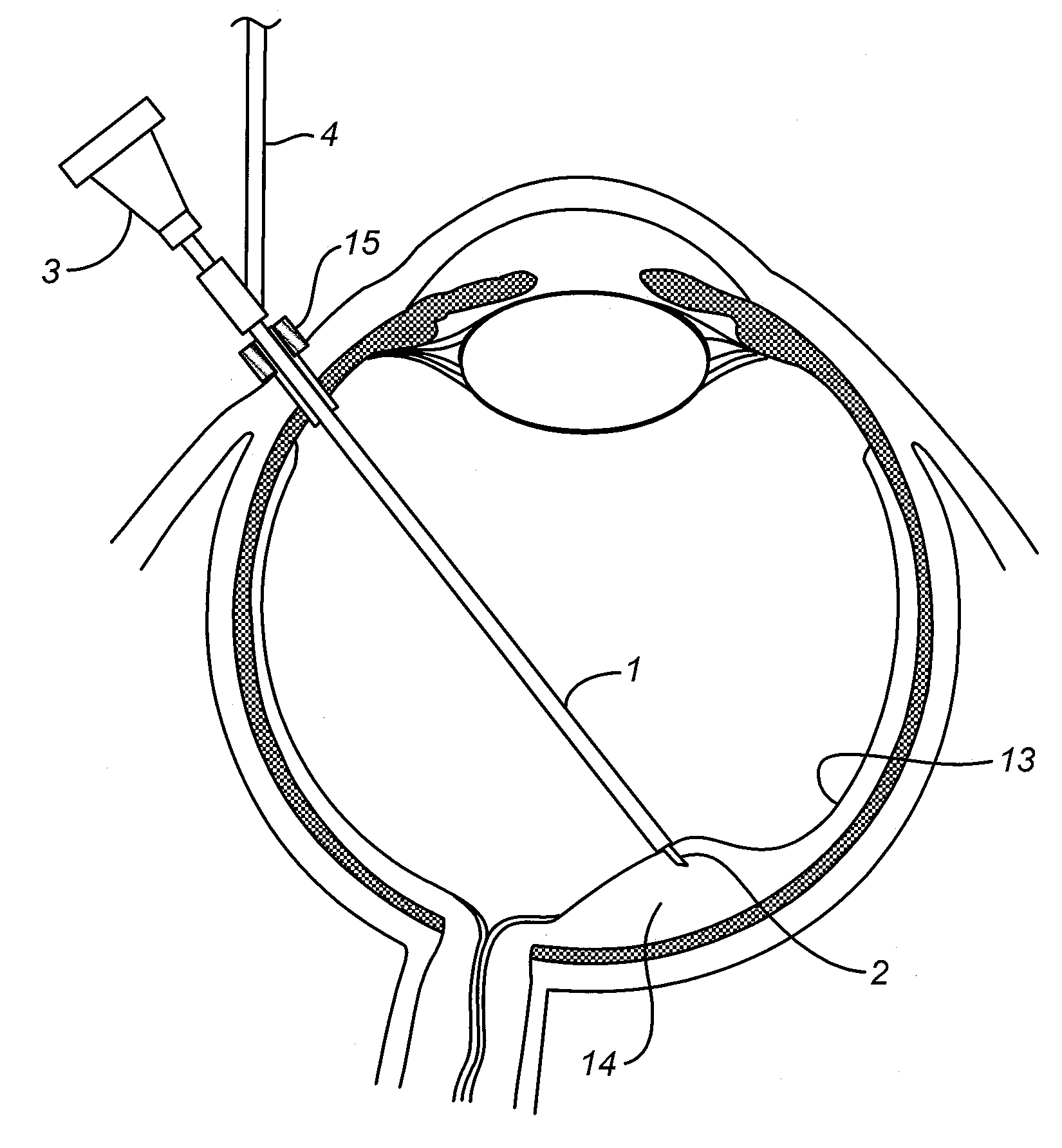
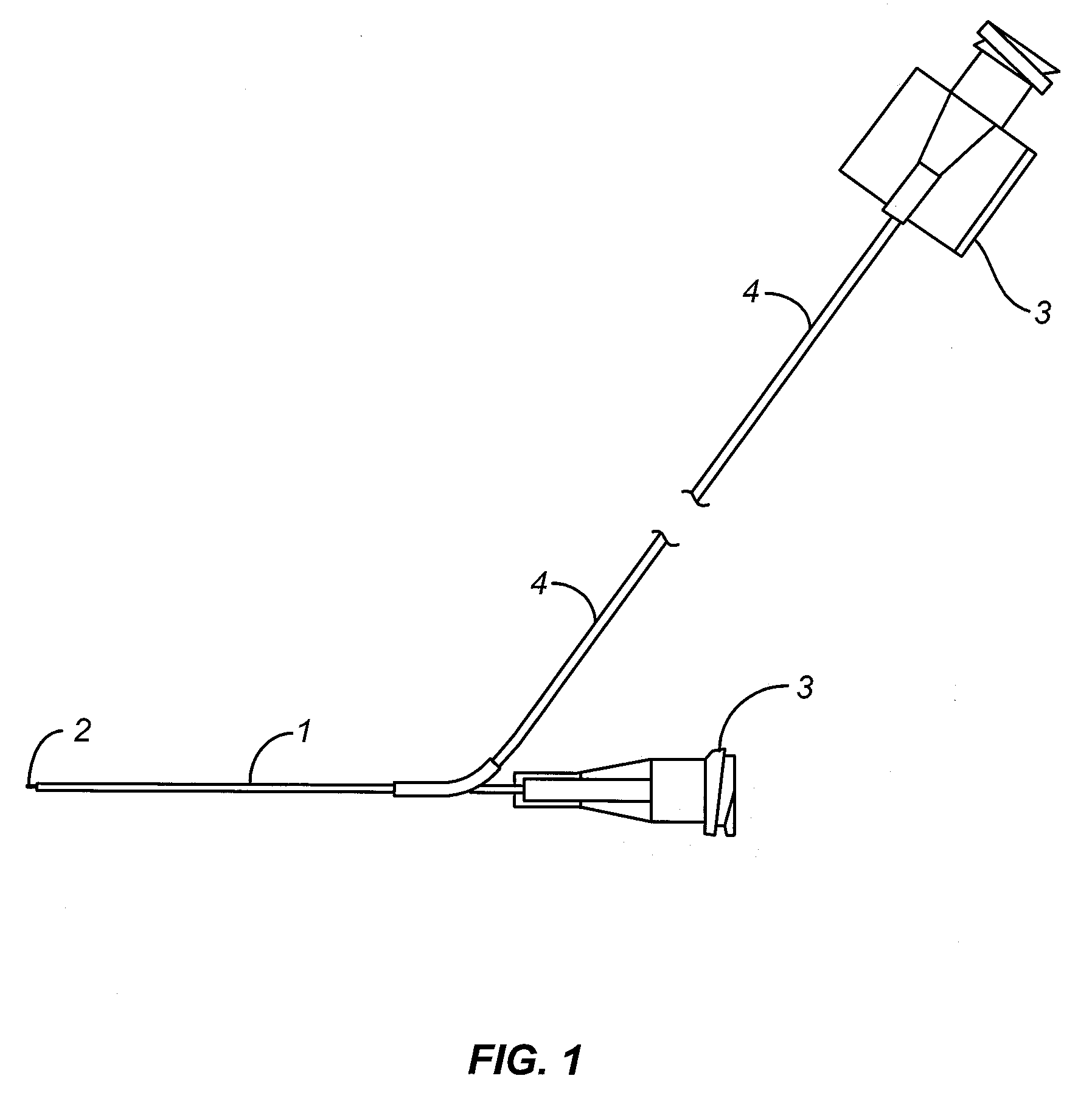
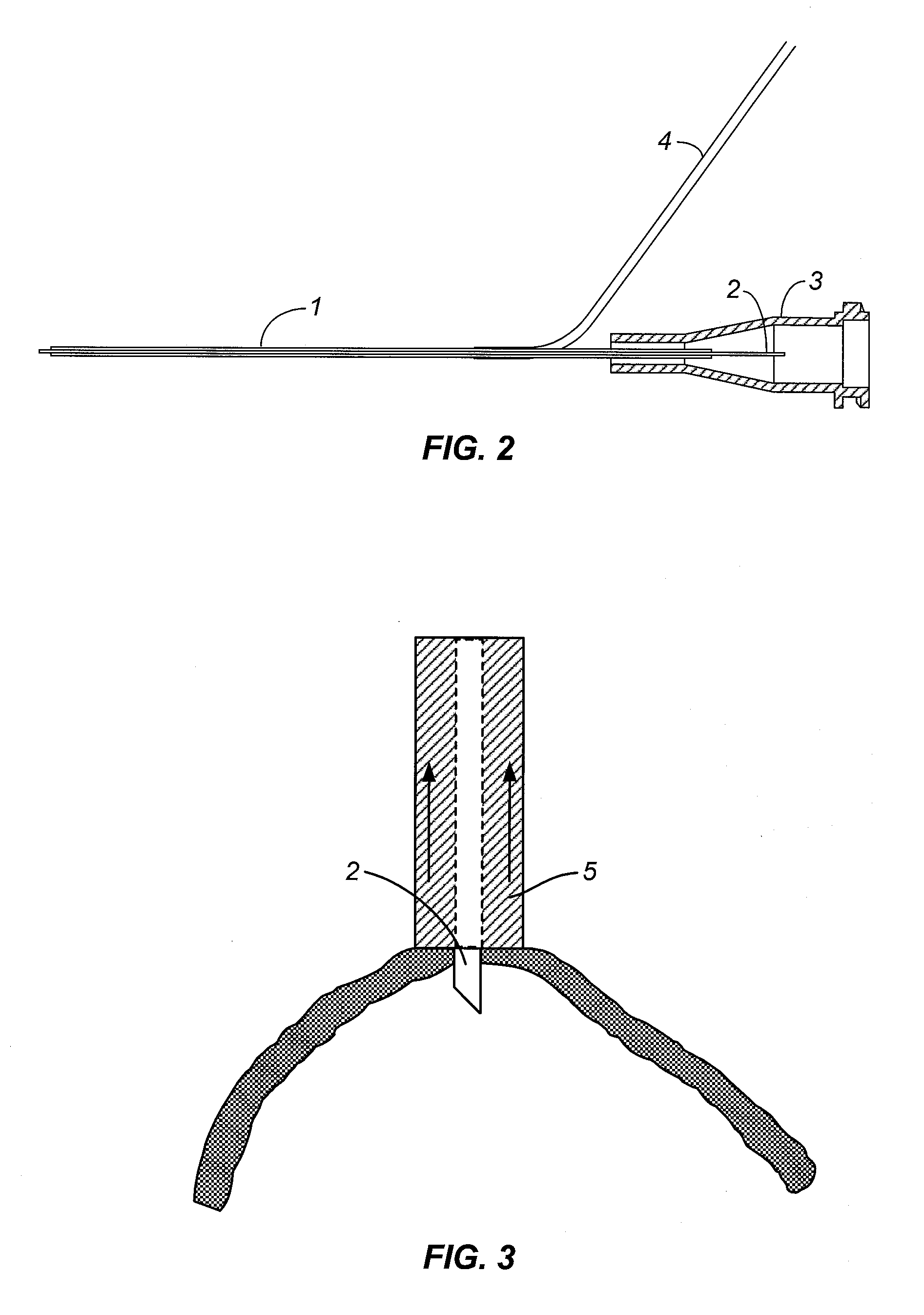
Access Device
[0056]Approximately 2″ of thin walled 25 Gauge stainless steel hypotube, 0.020″ by 0.012″, (MicroGroup, Inc) was used as the main shaft. A single hole was drilled approximately 1.25″ from the distal edge of the hypotube. A skive was created approximately 0.010″ from one end of a 3″ length of 0.020″ by 0.060″ Tygon tubing. The main shaft was inserted into the Tygon tubing through the skive until the hole of the main shaft was in communication with the Tygon tubing. UV cure cyanoacrylate adhesive (Loctite 4305, Loctite, Inc.) was applied at the proximal and distal interfaces between the Tygon tubing and the main shaft to create a seal, such that communication existed between the Tygon tubing branching from the main shaft and the lumen of the main shaft.
[0057]A 0.028″ stainless steel mandrel was heated with the proximal end of the Tygon tubing, and then fed into the proximal end of the Tygon tubing in order to flare the inner diameter of the Tygon tubing from 0.020″ to 0.0...
example 2
Laboratory Testing with the Access Device
[0061]A human cadaver eye was obtained from an eye bank. The cornea, the iris, natural lens, and the vitreous were removed, providing access to the retina from the interior of the globe without significantly damaging the retina tissue. The open globe was filled with phosphate buffered saline.
[0062]An access device as described in Example 1 was set-up as follows. The side port of the device was connected to a vacuum source to provide aspiration in the outer annulus. The vacuum source was capable of providing vacuum levels from 300 to 600 mm Hg. A 6 inch long extension tube was attached to Luer fitting in communication with the access shaft distal tip. A syringe containing 0.1% Alcian Blue dye was attached to the extension line.
[0063]In a first trial, the device tip was placed against a portion of the cadaver eye retina that had detached from the underlying RPE during preparation. Vacuum aspiration was applied to the outer annulus and its attac...
PUM
 Abstract
Description
Claims
Application Information