
Stator structure

a technology of stator and stator body, which is applied in the direction of windings, cooling/ventilation arrangements, dynamo-electric components, etc., can solve the problems of high-load steady running, deterioration of steep-hill climbing ability (gradeability), and motor coil temperature rise in use, so as to reduce the temperature of the coil, and reduce the effect of temperature ris

Active Publication Date: 2010-08-05
TOYOTA JIDOSHA KK
View PDF11 Cites 40 Cited by
  • Summary
  • Abstract
  • Description
  • Claims
  • Application Information

AI Technical Summary

Benefits of technology

[0005]The present invention has been made to solve the above problems and has a purpose to provide a stator structure with a coil molded with resin and a cooling structure providing low cost and high productivity.Means for Solving the Problems
[0012]For example, air or a cooling oil is directly sprayed to the exposed bus bar. Accordingly, the bus bar can be cooled efficiently. On the other hand, the heat generated in the coil covered by the resin molded portion will be conducted to the bus bar because of the high heat conductivity of the coil. The bus bar will heat to a temperature almost equal to the temperature of the coil. Accordingly, direct cooling the bus bar can provide an effect of directly cooling the coil covered by the resin molded portion, thus restraining a temperature increase of the coil. The bus bar is not molded with resin and hence an amount of resin for resin molding can be reduced largely.
[0013]Furthermore, the coil (a previously wound cassette coil portion) is resin-molded with its ends serving as terminals exposed and hence the coil portion of each coil can be protected against scratches. This can facilitate a work of wire-connecting the bus bars to the coil ends in later processes and enhance the productivity. Herein, coil terminals to be wire-connected are covered by separate protective caps or the like.
[0014]In the stator structure of the invention, the resin molded portion is formed with the uneven part for directing both ends of the bus bar to the coil terminals for wire connection. Accordingly, this makes it easy to attach the bus bars to the resin molded coils and further enhance the productivity.
[0015]In the stator structure of the invention, moreover, the split core on which the coil is mounted is molded with resin. It is therefore possible to resin-mold the coil with the coil ends being exposed and achieve a cost reduction.

Problems solved by technology

This may cause a problem in a temperature rise of the motor coil in use.
Consequently, there may occur problems of deterioration in steep-hill climbing capability (gradeability), high-load steady running, and others.

Method used


Image

  • Stator structure
  • Stator structure
  • Stator structure

Examples


Embodiment Construction

[0030]A detailed description of a preferred embodiment of a split core and a manufacturing method thereof for embodying a stator structure of the present invention will now be given referring to the accompanying drawings.

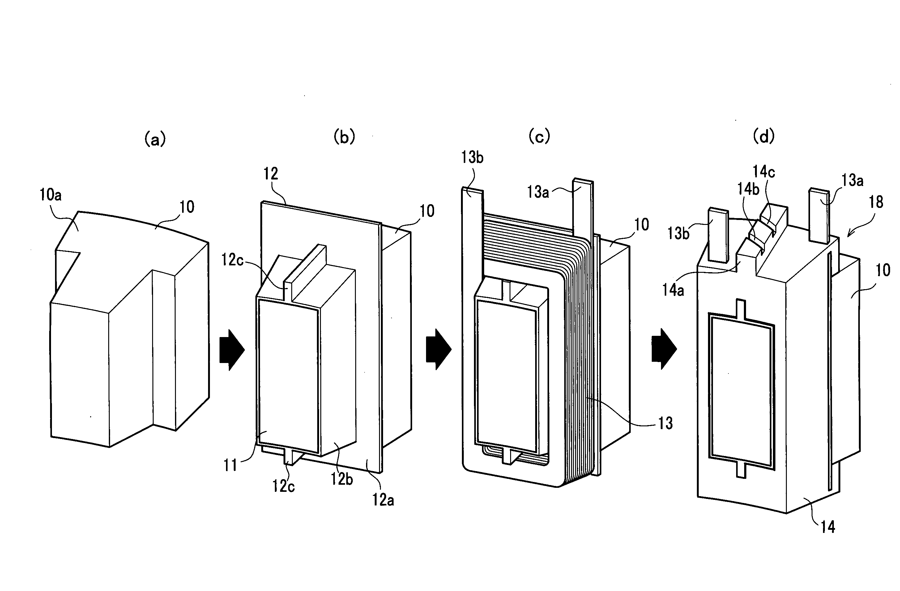
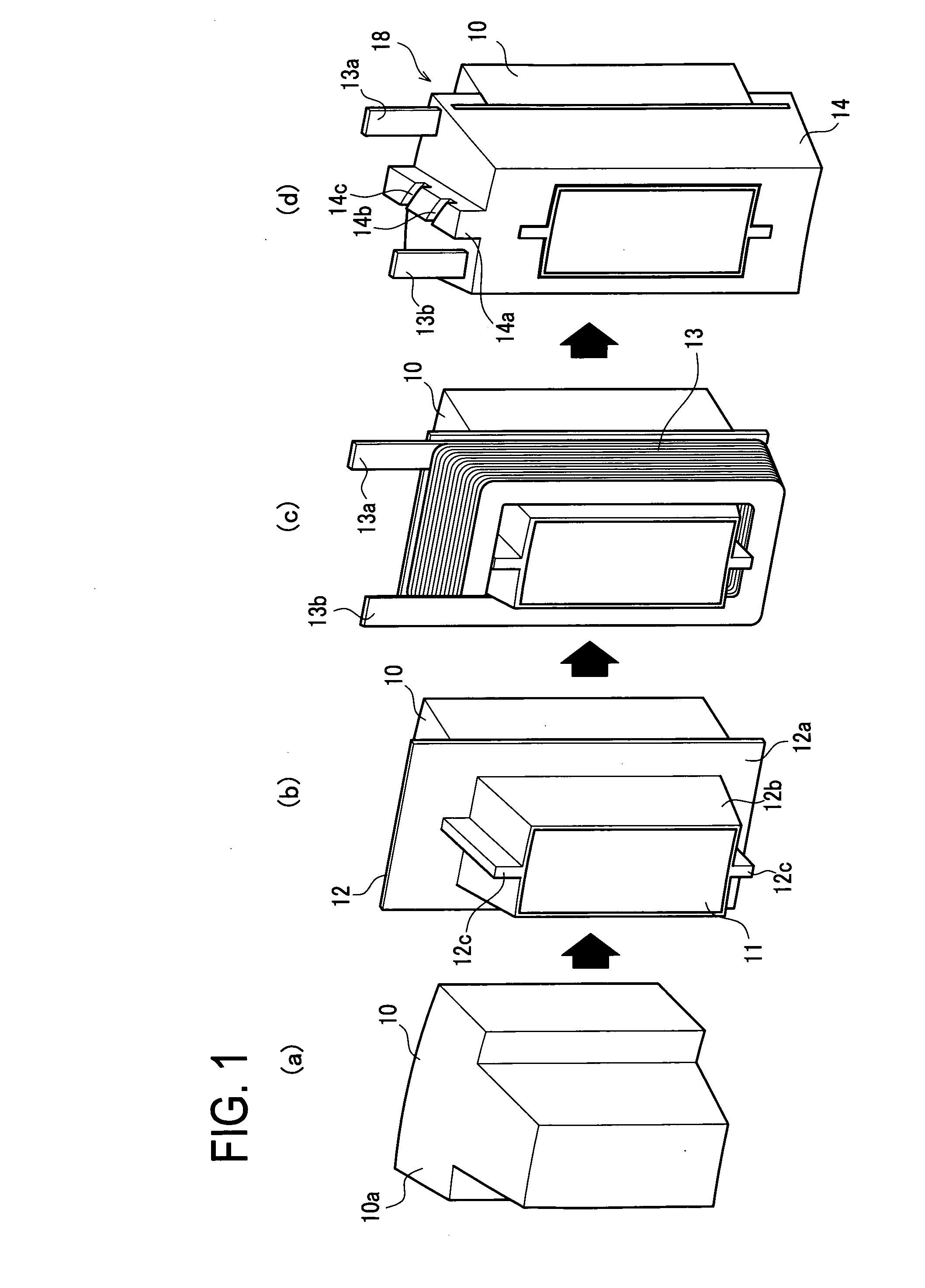
[0031]FIG. 1 shows a sequence of manufacturing a split stator. A split stator core (hereinafter, referred to as a “split core”) 1 includes an arc-shaped base portion 10a and a teeth 11 protruding therefrom so that a formed coil is to be mounted around the teeth 11. This split core 10 is made by laminating steel sheets produced by press-punching. Herein, eighteen split cores 10 are to be assembled together to form an annular stator core so that the arc-shaped base portions 10a are circularly arranged with the teethes 11 each protruding radially inwardly. This split core 10 is shown in a state (a) of FIG. 1. In a state (b) of FIG. 1, an insulator 12 is fitted on the teeth 11 of the split core 10. The insulator 12 includes a rectangular sleeve part 12b which covers the...


PUM


Abstract

A stator structure comprises an edgewise coil molded with resin with long ends being exposed, a bus bar connected to both ends of the coil ends, and a pump and injection holes for directly cooling the bus bar.

Description

TECHNICAL FIELD[0001]The present invention relates to a stator structure for a motor and more particularly to a stator structure with a high cooling capability.BACKGROUND ART[0002]A motor used in a hybrid electric vehicle outputs high power and has a high space factor of coil for reduction in motor size. This may cause a problem in a temperature rise of the motor coil in use. Accordingly, a demand has been increased for a method of cooling the coil at a high cooling efficiency. When the temperature of the coil rises, a limiter for upper limit temperature is activated for system safety. Consequently, there may occur problems of deterioration in steep-hill climbing capability (gradeability), high-load steady running, and others.[0003]JP2004-215358A discloses a technique of directly cooling by air flow an annular bus bar exposed on a coil with a heat conductive insulating member interposed therebetween.DISCLOSURE OF INVENTIONProblems to be Solved by the Invention[0004]However, if the t...

Claims


Application Information

Patent Timeline
IPC IPC(8): H02K3/32H02K9/19
CPCH02K3/522H02K5/08H02K15/12H02K9/19H02K5/20H02K5/203H02K9/22H02K3/24
Inventor TAKAHASHI, HIDEAKIKIYONO, TAKAAKINAKANISHI, KOJI
Owner TOYOTA JIDOSHA KK
Features
  • Generate Ideas
  • Intellectual Property
  • Life Sciences
  • Materials
  • Tech Scout
  • Unparalleled Data Quality
  • Higher Quality Content
  • 60% Fewer Hallucinations
Learn More