

Projection optical apparatus
a technology of optical apparatus and projection device, which is applied in the direction of projectors, telescopes, instruments, etc., can solve the problems of difficult to realize a compact projection device, the size of the apparatus becomes much more noticeable, and the space below the transmissive-refractive optical system provides an extensive dead spa
- Summary
- Abstract
- Description
- Claims
- Application Information
AI Technical Summary
Benefits of technology
Problems solved by technology
Method used
Image

Examples
first embodiment
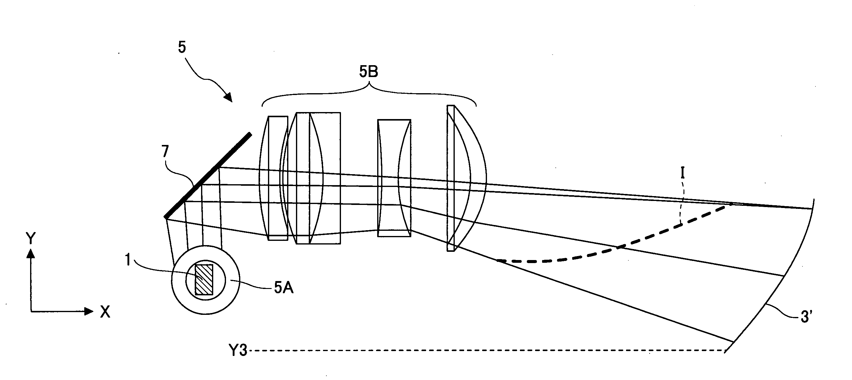
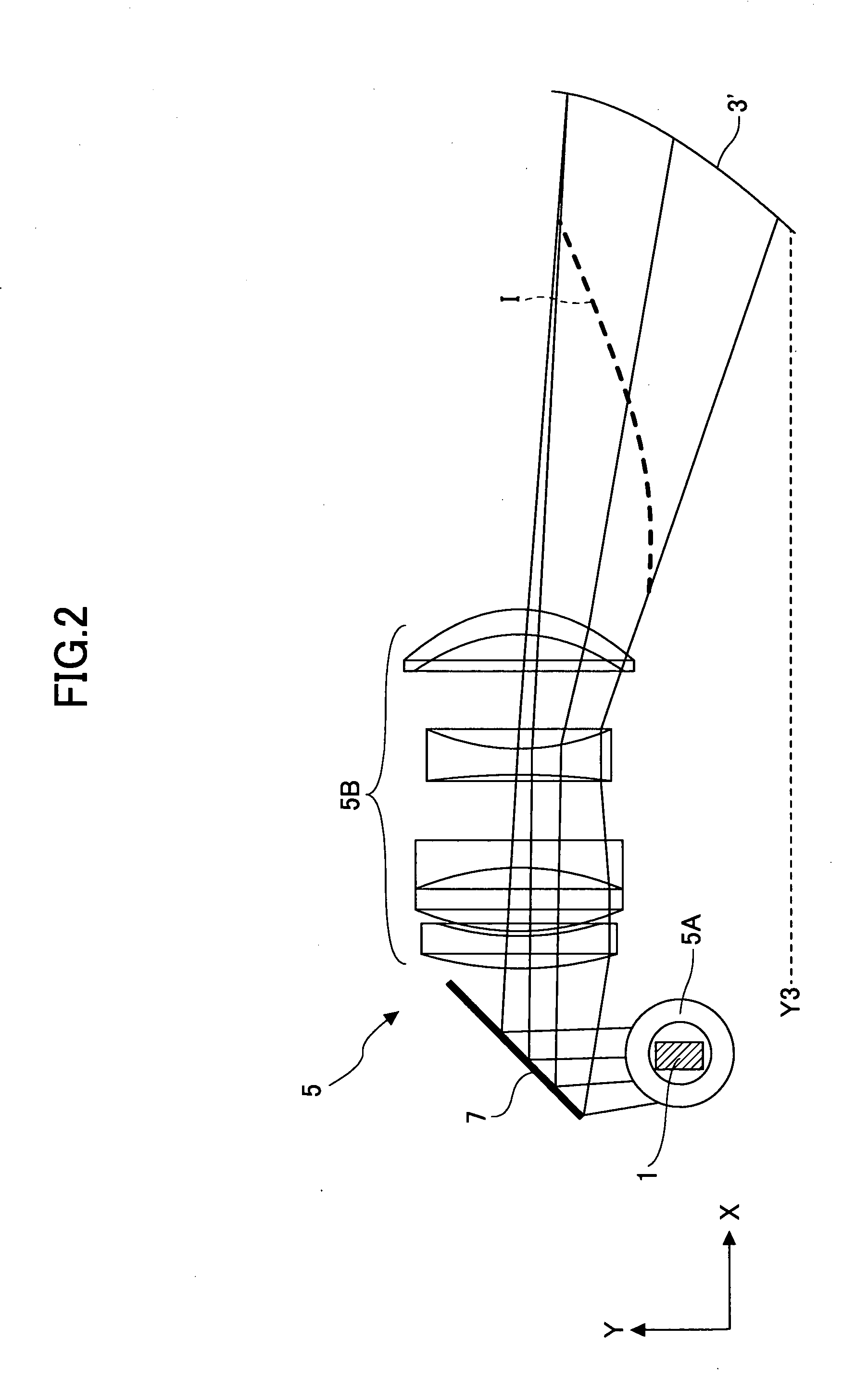
[0076]In the following, the invention is described, in which parts corresponding to those described with reference to FIG. 7 are referenced by corresponding numerals.
[0077]Before describing the present embodiment, vector A is defined in order to define a Y direction in an oblique projection optical apparatus according to the present embodiment.
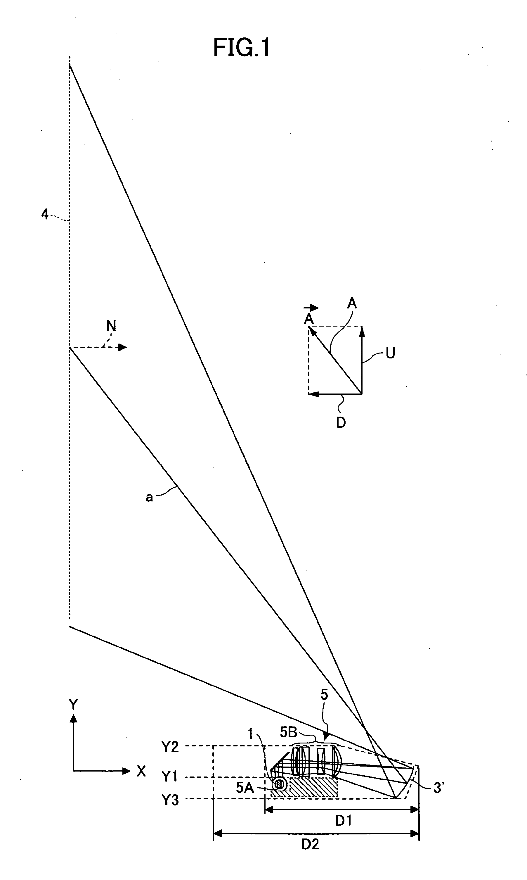
[0078]FIG. 1 shows a light beam a that travels along an optical path that leads from a second optical system 3′ to a projection surface 4 in an optical path between a center of an image formed on a spatial light modulator 1 and the projection surface 4. The light beam a is projected at an angle with respect to a normal N to the projection surface 4. In this case, even if there is a deflecting element along the path of the light beam a, the light beam a is assumed to pass through such a deflecting element in a straight line and reach the projection surface 4.
[0079]The vector of the light beam a in its direction of travel is defined as vector A,...
second embodiment
[0107]FIG. 8 shows the present invention, in which parts or elements corresponding to those of the foregoing embodiment are indicated with corresponding numerals, and the description of their structure or function are omitted unless necessary (the same applies to the subsequent embodiments).
[0108]In the present embodiment, an optical path deflecting unit 8 including two rectangular prisms that are integrally combined is employed. Specifically, the optical path deflecting unit 8 includes a first rectangular prism 9 and a second rectangular prism 10, which correspond to the optical path deflecting units 6 and 7, respectively, of the first embodiment. A normal to the deflecting surface 9A of the first rectangular prism 9 and a normal to the deflecting surface 10A of the second rectangular prism 10 are perpendicular to each other. Thus, as mentioned above, when the longitudinal direction of the spatial light modulator 1 is disposed in a direction normal to the base surface, the longitud...
third embodiment
[0112]FIG. 9 shows the invention.
[0113]In the present embodiment, cables 11 are drawn to the top surface side from spatial light modulators 1 from their shorter sides and connected to a control substrate 12. Thus, the control substrate 12 can be disposed parallel to the base surface easily.
[0114]In this arrangement, because the height of the apparatus is not constrained by the longitudinal or lateral length of the control substrate 12, the height of the apparatus can be made shorter than the longitudinal or lateral length of the control substrate 12.
[0115]While polarization beam splitters 13 are shown employed in the present embodiment, wire grid polarizers may be used instead. In FIG. 9, numeral 14 indicates a light-composing prism.
PUM
 Abstract
Description
Claims
Application Information