Fluidic configuration for flow injection analysis

a flow injection and configuration technology, applied in the field of flow injection configuration, can solve the problems of difficult to achieve without damage, non-integrated systems typically have relatively large dead volumes, and rarely are robust systems, so as to accelerate the rise and fall times, reduce dead volumes, and extend the kinetic range of real-time interaction analysis instruments.

Active Publication Date: 2010-08-05
SARTORIUS BIOANALYTICAL INSTR INC
View PDF12 Cites 13 Cited by
  • Summary
  • Abstract
  • Description
  • Claims
  • Application Information

AI Technical Summary

Benefits of technology

[0034]A fluidic configuration, both structural and methodological, for the injection of sample greatly reduces dead volume allowing rapid transition to 100% sample in a flow cell. For a continuous flow injection analysis system the structure and method provide counter flows to remove in one direction the dispersed region of the sample to waste before injecting non-dispersed sample into the flow cell by reversing the effective flow direction. The injection point itself is coplanar with the sensing surface and directly adjacent to the flow cell where all channels are microfluidic channels. Therefore, only the flow cell volume needs to be displaced during injection of sample in order to achieve 100% transition to sample within the flow cell. This greatly accelerates the rise and fall times thereby extending the kinetic range of the real-time interaction analysis instrument. In addition such rapid transition to sample improves overall data quality thereby improving kinetic model fitting.

Problems solved by technology

Despite much progress these systems are rarely as robust as conventional flow injection analysis fluidic systems where the active components are not integrated into the fluidic card; however, these non-integrated systems typically have relatively large dead volumes.
Permanent attachment of a flow channel to the SPR active sensing region is possible but this can be difficult to achieve without damaging the surface chemistry attached to the active sensing region.
Damage can occur due to chemical and / or mechanical damage during the flow channel attachment process.
In addition, making reliable, and reversible, fluid connections with the flow channel inputs is difficult.
Therefore, flow channel heights below 15 μm are not practical for low pressure systems.
In addition, flow channels below this height are easily blocked by particulates that are often present in unfiltered samples and buffers.
In addition excess backpressure causes delays in reaching a steady-state flow.
Such delays have significant effects on the performance of the biosensor system.
If a bulk refractive index variation exists between the running buffer and sample, then the response due to this bulk index response is difficult to resolve from the actual binding signal, without using a reference channel, unless the exchange time can be reduced (i.e., to less than 10 seconds).
These velocity gradients cause uneven distribution of analyte binding at the surface.
Turbulent flow will exist at the inlet and outlet causing unpredictable analyte binding.
Depending on the volume of this region of flow and the flow rate, this displacement may require significant time to carry analyte in the sample across the sensing region.
This gradient can be difficult to account for when processing the data obtained from the flow cell.
A time delay between channels may be accounted for during processing; however, the additional dispersion that occurs in this interchannel dead volume can give rise to response variations between channels if any bulk refractive index difference exists between the sample and the running buffer.
In practice such bulk refractive index differences can be expected and reference curve subtraction will therefore introduce artifacts.
Thus, such delays decrease the reproducibility of binding responses from one SPR channel to the next and also make reference subtraction more difficult.
This reference subtraction method will not be effective if a large dead volume, and hence significant dispersion, exists between both flow channels.
If these dead volumes are large, then the injected sample will suffer from dispersion for a considerable portion of the injection.
Any disruptions caused by bubbles will prevent normal operation making the system less robust, requiring expensive degassing devices.
Furthermore a means of controlling the flow rate in multiple streams adds additional pump drives that introduce considerable expense.

Method used


Image

  • Fluidic configuration for flow injection analysis
  • Fluidic configuration for flow injection analysis
  • Fluidic configuration for flow injection analysis

Examples


example

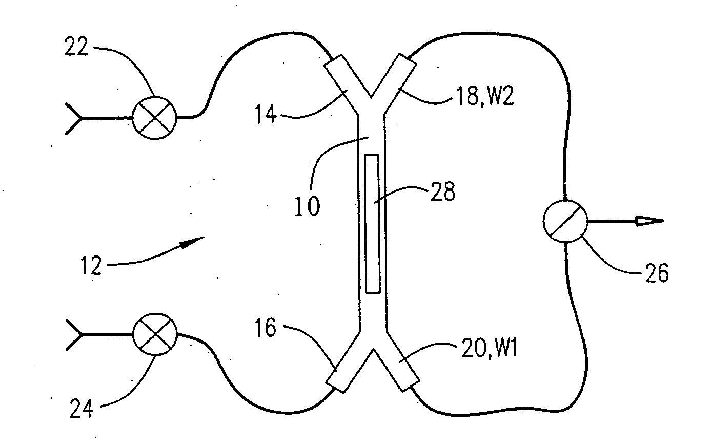
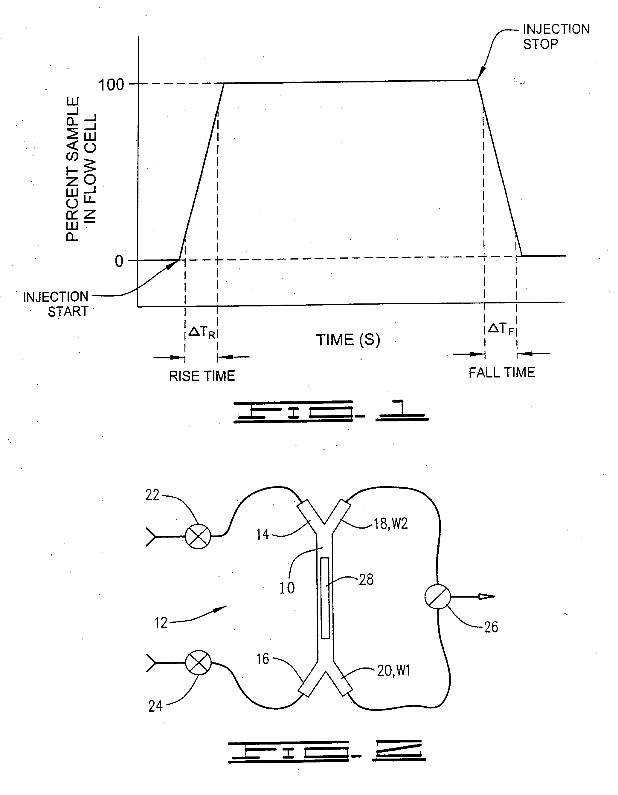
[0082]A flow injection system was configured according to the invention as described in FIG. 2. The flow cell volume was approximately 30 nL. Water was flowed from inlet port 14 and exited the channel at waste port 20. Sample (i.e. 10% dimethylsulfoxide in water) was flowed from inlet port 16 and exited at waste port 20. In this configuration water was in contact with the sensing surface 28. The sensor response is plotted as a function of time (data rate of 10 Hz) in FIG. 11. During this period the dispersed (i.e. mixed) segment of the sample is allowed flow to waste port 20. Under our fluidic configuration at least 5 μL of sample was dispensed to waste before the sample was injected. The sensor response (which records the refractive index at the sensing surface 28) remains constant until the sample is injected. The injection over the sensing surface 28 was actuated by simultaneously opening waste port 18 and closing waste port 20. This causes an immediate reversal in the direction ...


PUM

PropertyMeasurementUnit
diametersaaaaaaaaaa
heightsaaaaaaaaaa
heightsaaaaaaaaaa

Abstract

A fluidic configuration, both structural and methodological, for the injection of sample greatly reduces dead volume allowing rapid transition to 100% sample in a flow cell. For a continuous flow injection analysis system the structure and method provide counter flows to remove in one direction the dispersed region of the sample to waste before injecting non-dispersed sample into the flow cell by reversing the effective flow direction. The injection point itself is directly adjacent to the flow cell where all channels are microfluidic channels. Therefore, only the flow cell volume needs to be displaced during injection of sample in order to achieve 100% transition to sample within the flow cell. This greatly accelerates the rise and fall times thereby extending the kinetic range of the real-time interaction analysis instrument. In addition such rapid transition to sample improves overall data quality thereby improving kinetic model fitting.

Description

FIELD OF THE INVENTION[0001]The present invention relates to fluidic systems and methods with which to inject flows of fluids relative to sensing regions. One particular field of application is microfluidic biosensing using biomolecular ligands and analytes.BACKGROUND OF THE INVENTION[0002]Analytical instruments such as biosensors are well established as a means of recording the progress of biomolecular interactions in real time. Biosensors are analytical instruments that employ a variety of transduction technologies in order to detect interactions between biomolecules. Such instrumentation requires microfluidic channels in order to deliver samples to a sensing region. Pumps and valves are preferred to provide a means of moving sample through the channels in a controlled reproducible manner.[0003]Recent interest in microfluidics technology has come about because of a growing need for sophisticated control of fluid streams for such sensing applications. A number of prior systems, ref...

Claims


Application Information

Patent Timeline
Patent Type & Authority Applications(United States)
IPC IPC(8): G01N35/10G01N1/10G01N35/08B81B7/00
CPCY10T436/11G01N35/1095G01N2035/00158B01L3/502761B01L2300/0636B01L2300/0816B01L2300/0851B01L2400/0622
Inventor QUINN, JOHN GERARD
Owner SARTORIUS BIOANALYTICAL INSTR INC
Why Eureka
Try Eureka