Method for separating carbon dioxide from flue gases and associated device

a technology of carbon dioxide and flue gas, which is applied in the direction of separation processes, hydrogen sulfides, sulfur compounds, etc., can solve the problems of high energy requirements for regeneration, slippage of substances, and inability to solve existing plants

Inactive Publication Date: 2010-08-05
SIEMENS AG
View PDF5 Cites 9 Cited by
  • Summary
  • Abstract
  • Description
  • Claims
  • Application Information

AI Technical Summary

Benefits of technology

[0013]Starting from this basis, the object of the invention is to propose an improved method for the large-scale reduction in emissions of carbon dioxide (CO2) and ...

Problems solved by technology

The latter is however not a solution for existing plants which are designed to use high-carbon fuels, such as lignite-fired power plants in particular.
Potential problems in this situation are the slippage of the substance required for the binding, in other words the absorber, the separation of the CO2 from the scrubbing gas in a form which permits the further use of the CO2, and where applicable the high energy requirement for the regeneration, particularly in the case of chemical binding.
A problem...

Method used


Image

  • Method for separating carbon dioxide from flue gases and associated device
  • Method for separating carbon dioxide from flue gases and associated device
  • Method for separating carbon dioxide from flue gases and associated device

Examples


Embodiment Construction

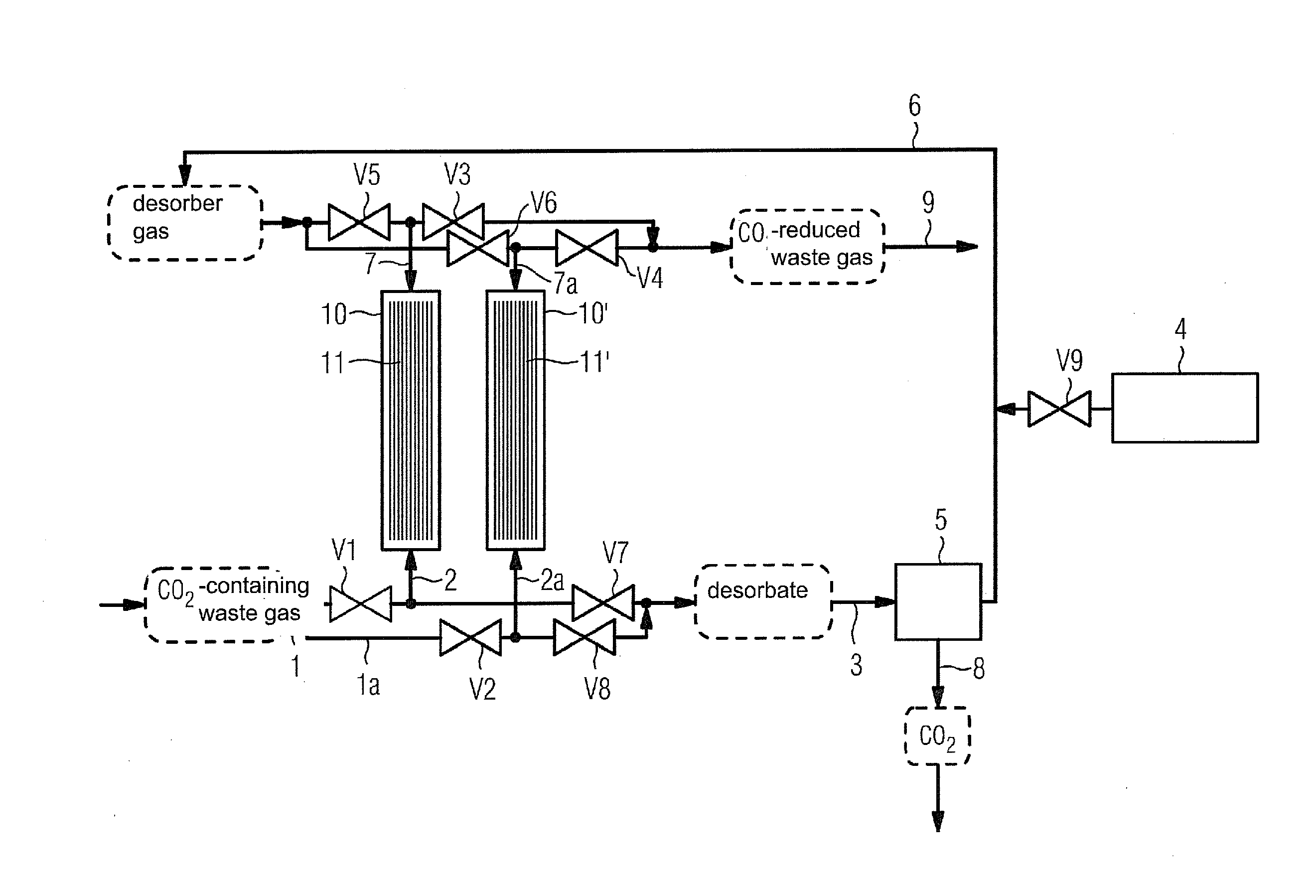
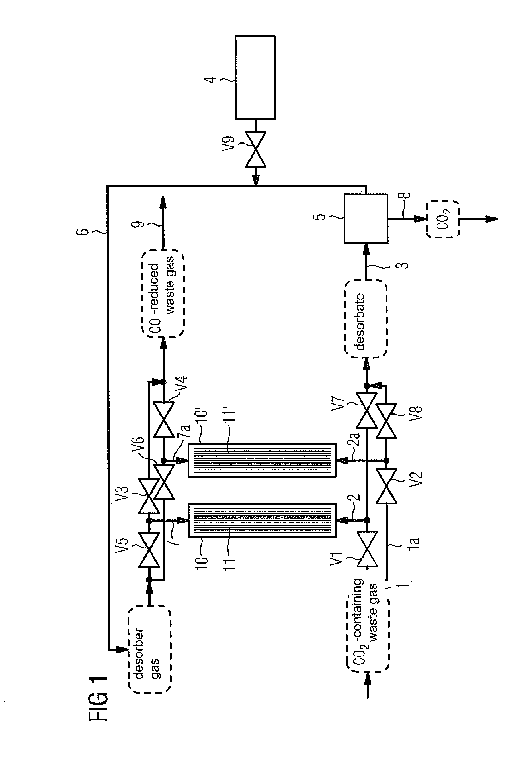
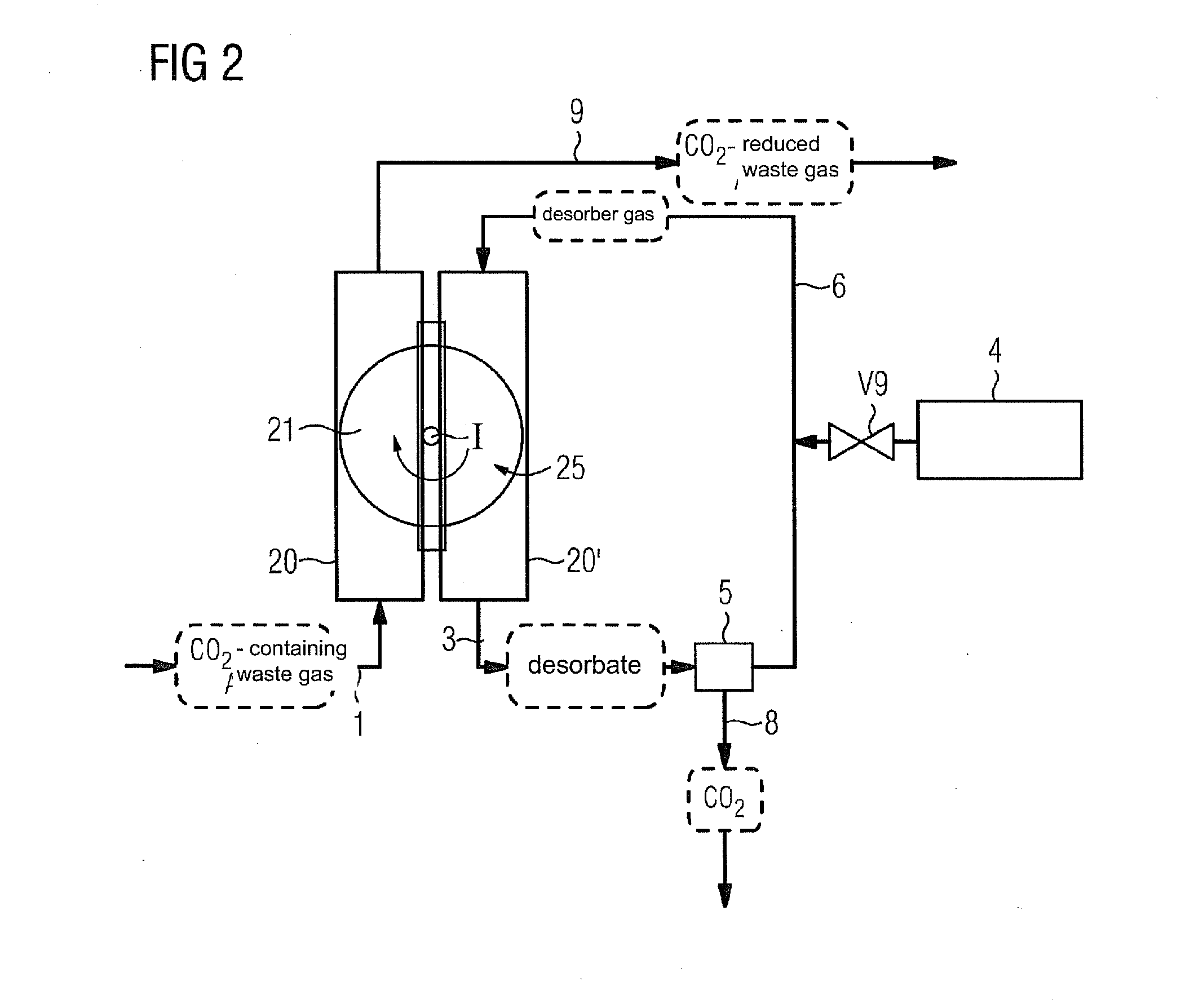
[0039]In the following, the two figures are described individually in each case. In this situation the essential elements, such as the reactors and valves including the lines which comprise the same function have the same reference characters.

[0040]With regard to the FIGS. 1 to 3, two identical reactors 10 and 10′, 20 and 20′, and 30 and 30′ respectively are present in each case, which are run in alternating operation. In other words, for example for

[0041]FIG. 1, while the one of the two reactors 10, 10′ is used for the adsorption of the CO2 in the waste gas containing CO2, the other of the two reactors 10, 10′ is discharged, which is described in detail further below. For such a type of alternating operation, fluid lines with a series of valves are required as well as additionally a storage container for an absorption agent for CO2 and a unit for separating the CO2 from the regenerate.

[0042]The two reactors 10 and 10′ in FIG. 1 each have a respective catalyst bed 11 and 11′. Waste ...


PUM

PropertyMeasurementUnit
Temperatureaaaaaaaaaa

Abstract

A method in which CO2 is placed on an adsorber and an adsorption reaction with ammonia, that is used as a chemical absorption agent, occurs, is provided. The CO2 extracted from the waste gas is joined to the ammonia on the catalytic surface using a heterogeneous, catalytic reaction. At least two reactors are provided in the associated device. The reactors, which operate alternately, are switched between the adsorption of CO2 and the regeneration of the absorption agent.

Description

CROSS REFERENCE TO RELATED APPLICATIONS[0001]This application is the US National Stage of International Application No. PCT / EP2008 / 058240, filed Jun. 27, 2008 and claims the benefit thereof. The International Application claims the benefits of German application No. 10 2007 030 069.9 DE filed Jun. 29, 2007, both of the applications are incorporated by reference herein in their entirety.FIELD OF INVENTION[0002]The invention relates to a method for separating carbon dioxide (CO2) from flue gases by using an adsorption method, wherein the CO2 is accumulated on an adsorber. In addition, the invention relates to an associated device for executing the method.BACKGROUND OF INVENTION[0003]The reduction in the emission of the greenhouse gas carbon dioxide (CO2) from power plants and industrial plants can be achieved through the use of low-carbon fuels.[0004]The latter is however not a solution for existing plants which are designed to use high-carbon fuels, such as lignite-fired power plants...

Claims


Application Information

Patent Timeline
IPC IPC(8): B01D53/62B01D53/86B01J8/00C01B31/20C01B32/50
CPCB01D53/864B01D2253/108B01D2255/20707Y02C10/04B01D2257/504B01D2258/06B01D2255/20723Y02C20/40
Inventor HAMMER, THOMASHARTMANN, WERNER
Owner SIEMENS AG
Why Eureka
Try Eureka