
Magnesium alloy material, and method for treatment of surface of magnesium alloy material

a magnesium alloy material and surface treatment technology, applied in the direction of transportation and packaging, chemistry apparatus and processes, etc., can solve the problems of increased cost and increase in the number of steps, difficulty in using solutions, and insatiable efficiency of surface treatment, etc., to achieve excellent corrosion resistance, reduce cost and increase the effect of surface treatmen

Inactive Publication Date: 2010-08-05
NAT INST OF ADVANCED IND SCI & TECH
View PDF7 Cites 0 Cited by
  • Summary
  • Abstract
  • Description
  • Claims
  • Application Information

AI Technical Summary

Benefits of technology

[0023]The present invention is attained in view of the above problems. An object of the present invention is to provide a magnesium alloy material having excellent corrosion resistance, shock resistance and the like, and to provide a surface treatment method of magnesium alloy material allowing the manufacture of a magnesium alloy material having excellent corrosion resistance, shock resistance and the like.
[0050]This way, it becomes possible to manufacture a magnesium alloy material having excellent corrosion resistance, shock resistance and the like, such excellent corrosion resistance, shock resistance and the like being impossible to obtain using conventional surface treatment methods.

Problems solved by technology

As a result, it is difficult to use the solution repeatedly after the surface treatment, and problems such as a cost increase and an increase in the number of steps occur.
However, because the magnesium alloy material is only put in contact with the steam and several other steps (such as degreasing, coating or blast treatment) are necessary, such a problem occurs that the surface treatment does not have a satisfying efficiency.
In addition, with a surface treatment method in which a magnesium alloy material is treated using a generally used anodic oxidation method, because the anodic oxidation is performed by having an electric current pass into a solution, the following problems occur: a high potential is required if a coated layer of a surface of the magnesium alloy becomes thick, and because of this, a large-scale surface treatment device is necessary.
Further, with the anodic oxidation method, because the coated layer is only attached onto the surface of the magnesium alloy material, the coated layer of the surface of the magnesium alloy material becomes cracked if the magnesium alloy material is bent.
As a result, such a problem occurs that the magnesium alloy material on which the coated layer is attached by anodic oxidation cannot be easily put to practical use.

Method used


Image

  • Magnesium alloy material, and method for treatment of surface of magnesium alloy material
  • Magnesium alloy material, and method for treatment of surface of magnesium alloy material
  • Magnesium alloy material, and method for treatment of surface of magnesium alloy material

Examples


example 1

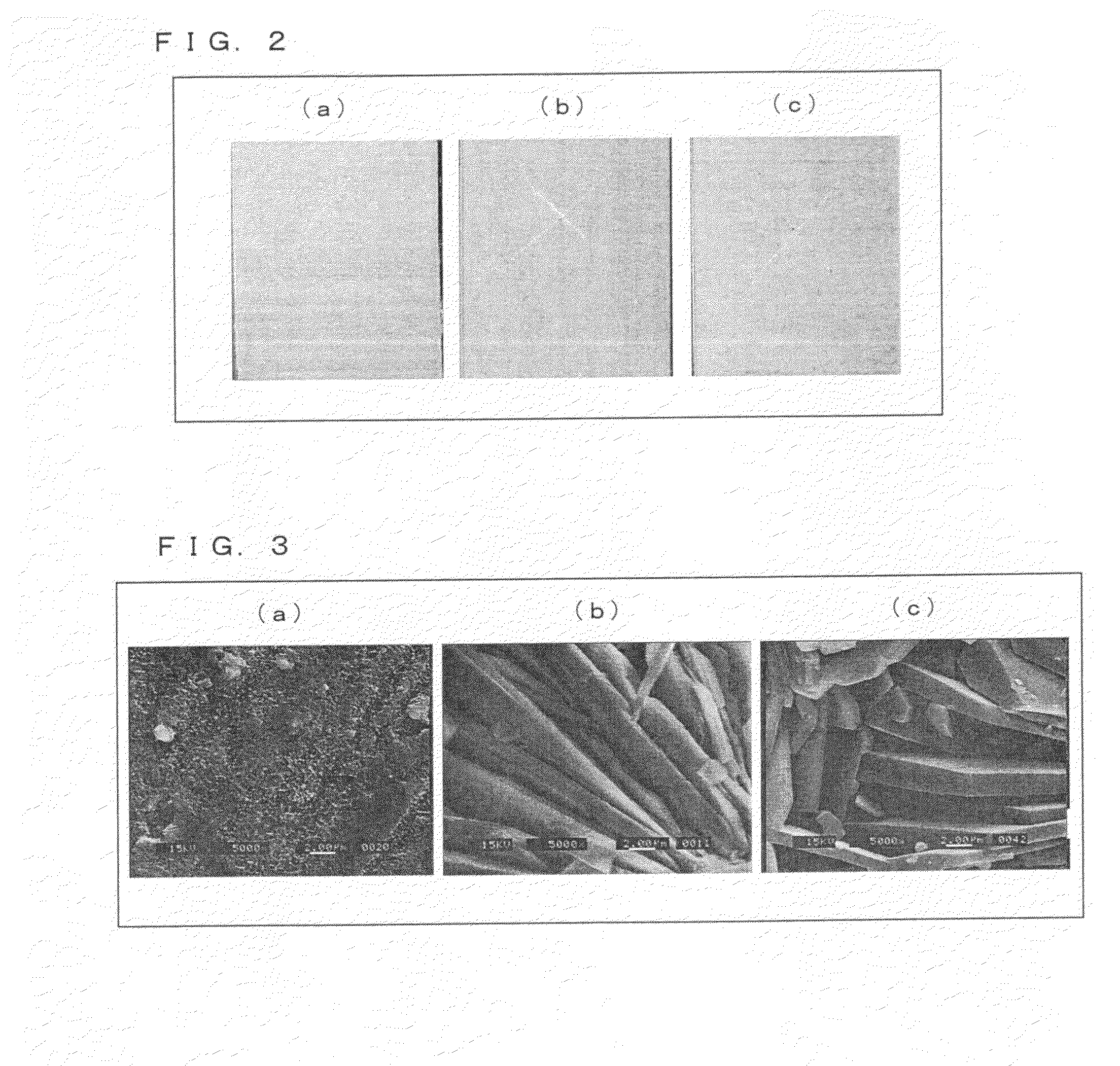
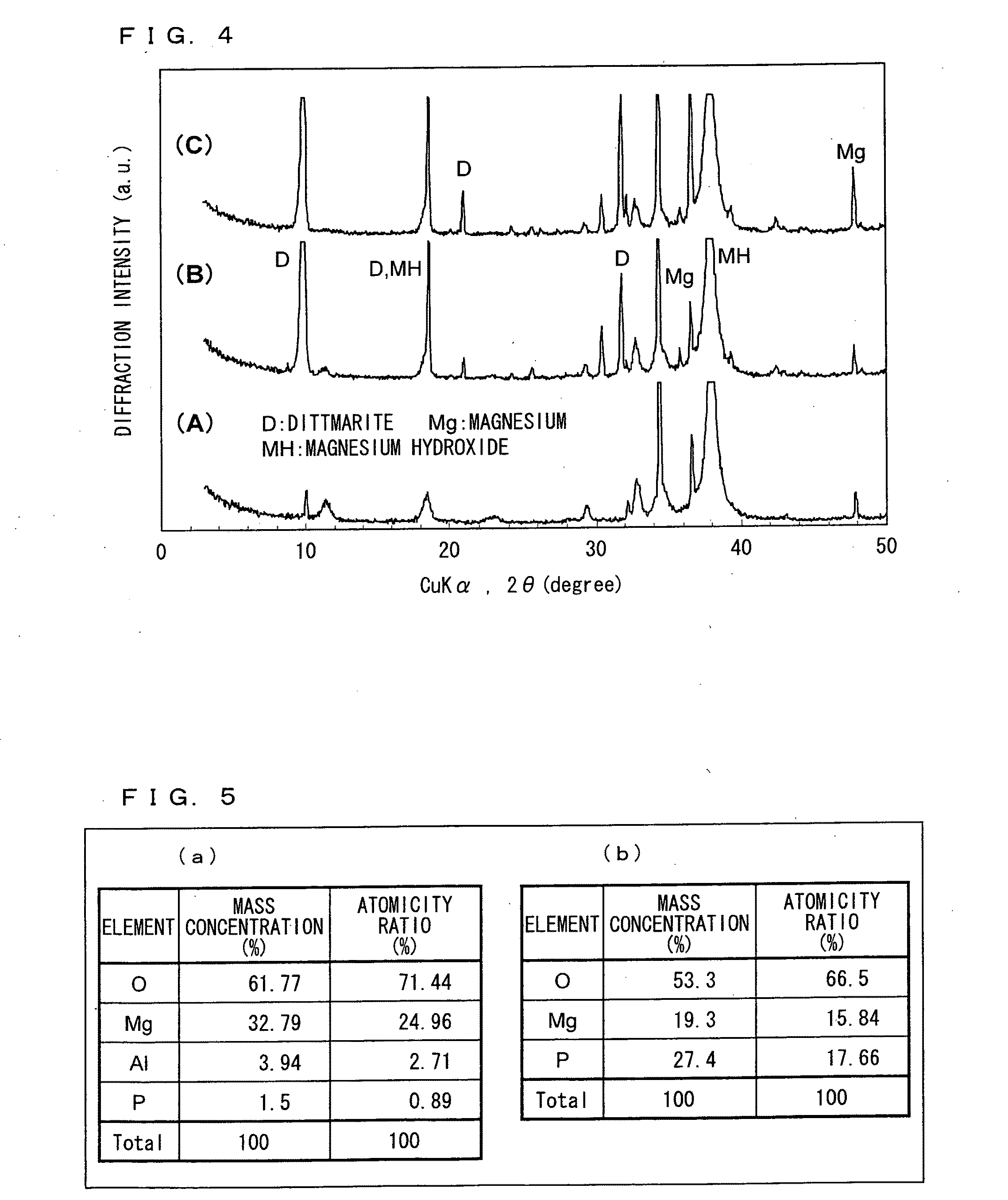
[0112]The magnesium alloy material was put in the steam curing device at 140° C., and was treated using a 20% diammonium hydrogen phosphate solution during 24 hours. Post-treatment thickness, hardness and corrosion resistance are shown in Table 1. The test sample after immersion in the salt water solution is shown on (a) of FIG. 2. Results of an SEM observation of the test sample after steam curing are shown on (a) of FIG. 3. As shown on (a) of FIG. 3, small crystals were observable after steam curing. Further, as can be seen in the X-ray diffraction diagram in FIG. 4, peaks of dittmarite slightly appear, and peaks of magnesium hydroxide clearly appear (A of FIG. 4). Further, thanks to results of an elementary analysis shown in (a) of FIG. 5, it was understood that phosphate (P) has a 1.5% mass concentration.

example 2

[0113]After the magnesium alloy material had been put in contact with a 10% diammonium hydrogen phosphate solution at 120° C. during 2 hours, a resulting material was introduced in the steam curing device at 140° C., and treated using a 20% diammonium hydrogen phosphate solution during 24 hours. Post-treatment thickness, hardness and corrosion resistance are shown in Table 1. The test sample after immersion in the salt water solution is shown on (b) of FIG. 2. Results of an SEM observation of the test sample after steam curing are shown on (b) of FIG. 3. As shown on (b) of FIG. 3, tabular crystals, were observable after steam curing. Further, in the X-ray diffraction diagram in FIG. 4, peaks of dittmarite and peaks of magnesium hydroxide clearly appear (B of FIG. 4).

example 3

[0114]After the magnesium alloy material had been put in contact with a 20% diammonium hydrogen phosphate solution at 120° C. during 2 hours, a resulting material was introduced in the steam curing device at 140° C., and treated using 20% diammonium hydrogen phosphate solution during 24 hours. Post-treatment thickness, hardness and corrosion resistance are shown in Table 1. The test sample after immersion in the salt water solution is shown on (c) of FIG. 2. Results of an SEM observation of the test sample after steam curing are shown on (c) of FIG. 3. As shown on (c) of FIG. 3, tabular crystals were observable after steam curing. Further, in the X-ray diffraction diagram in FIG. 4, peaks of dittmarite and peaks of magnesium hydroxide clearly appear (C of FIG. 4). Further, thanks to results of an elementary analysis shown in (b) of FIG. 5, it was understood that phosphate (P) has a 27.4% mass concentration.


PUM

PropertyMeasurementUnit
Temperatureaaaaaaaaaa

Abstract

A magnesium alloy material contains a complex made from a phosphate-containing magnesium, such as dittmarite and the like, and magnesium hydroxide, the complex being formed by a steam curing of the magnesium alloy material conducted using (i) at least one compound chosen among diammonium hydrogen phosphate, ammonium dihydrogen phosphate, and triammonium phosphate, and (ii) water. In this way, it is possible to provide a magnesium alloy material having excellent corrosion resistance, shock resistance and the like, and to provide a method for treatment of surface of magnesium alloy material allowing the manufacture of a magnesium alloy material having excellent corrosion resistance, shock resistance and the like.

Description

TECHNICAL FIELD[0001]The present invention relates to a magnesium alloy material and to a method for treatment of a surface of a magnesium alloy material (surface treatment method). More precisely, the present invention relates (i) to a magnesium alloy material having a surface on which a phosphate-containing component having good crystallinity, such as dittmarite and the like, is formed, and then is subjected to steam curing with diammonium hydrogen phosphate or the like so as to form a strong coating layer containing a composite of phosphate-containing magnesium, such as dittmarite and the like, and magnesium hydroxide, and (ii) to a surface treatment method allowing the formation of a phosphate-containing compound having good crystallinity, such as dittmarite and the like, on the surface of the magnesium alloy material, and performing steam curing conducted using diammonium hydrogen phosphate, so as to form a strong coating layer containing composite phosphate-containing magnesiu...

Claims


Application Information

Patent Timeline
IPC IPC(8): B32B15/04B05D3/04B05D3/02
CPCC22C1/002C25D11/30C23C22/08Y10T428/31678C22C1/11
Inventor TSUNEMATSU, KINUEINOUE, KOZOTSUNEMATSU, SHUJISAKAMOTO, MICHIRU
Owner NAT INST OF ADVANCED IND SCI & TECH
Learn More