Catalyst ink, method for producing catalyst ink, method for producing membrane-electrode assembly, membrane-electrode assembly produced by the method, and fuel cell
- Summary
- Abstract
- Description
- Claims
- Application Information
AI Technical Summary
Benefits of technology
Problems solved by technology
Method used
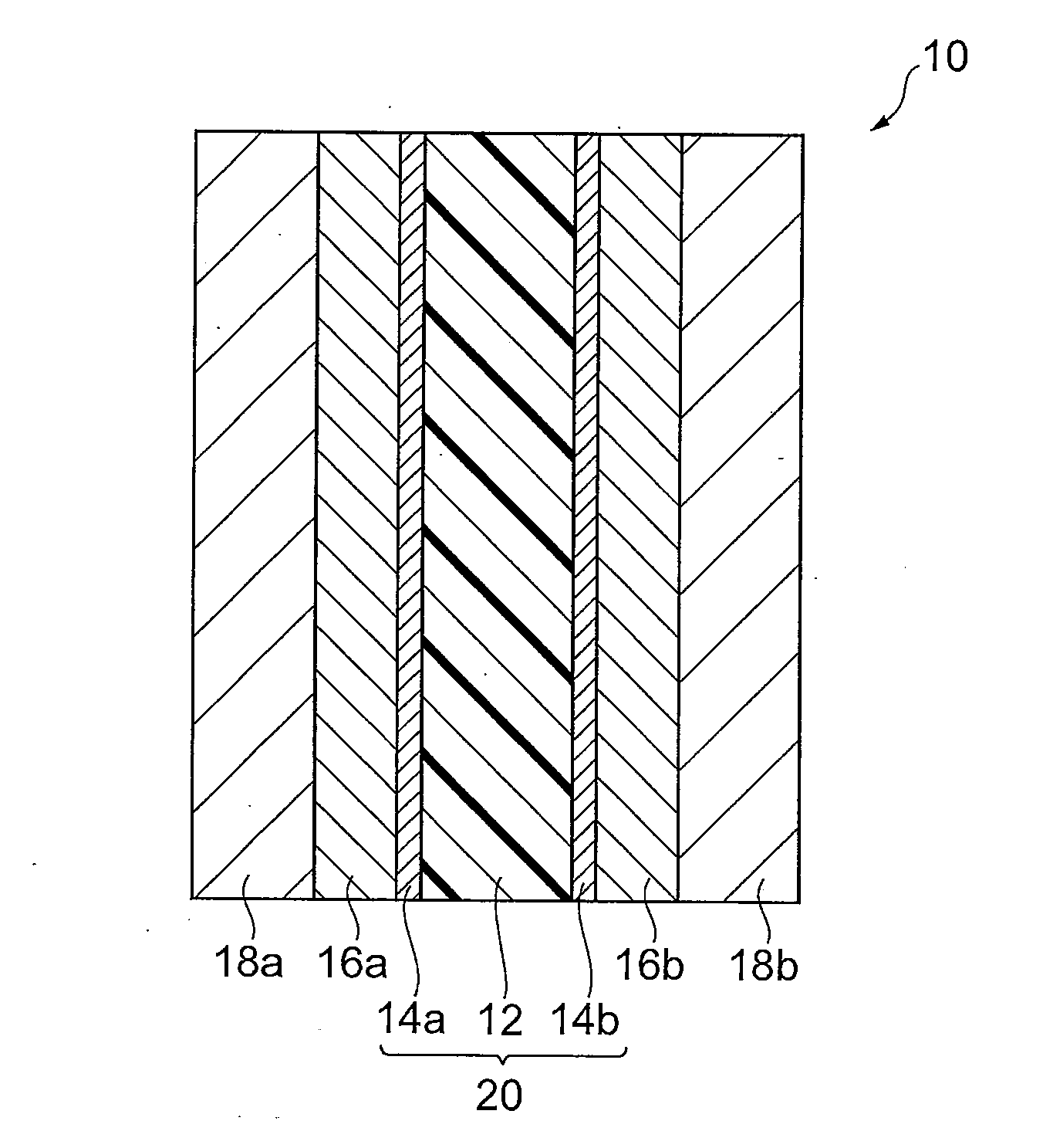
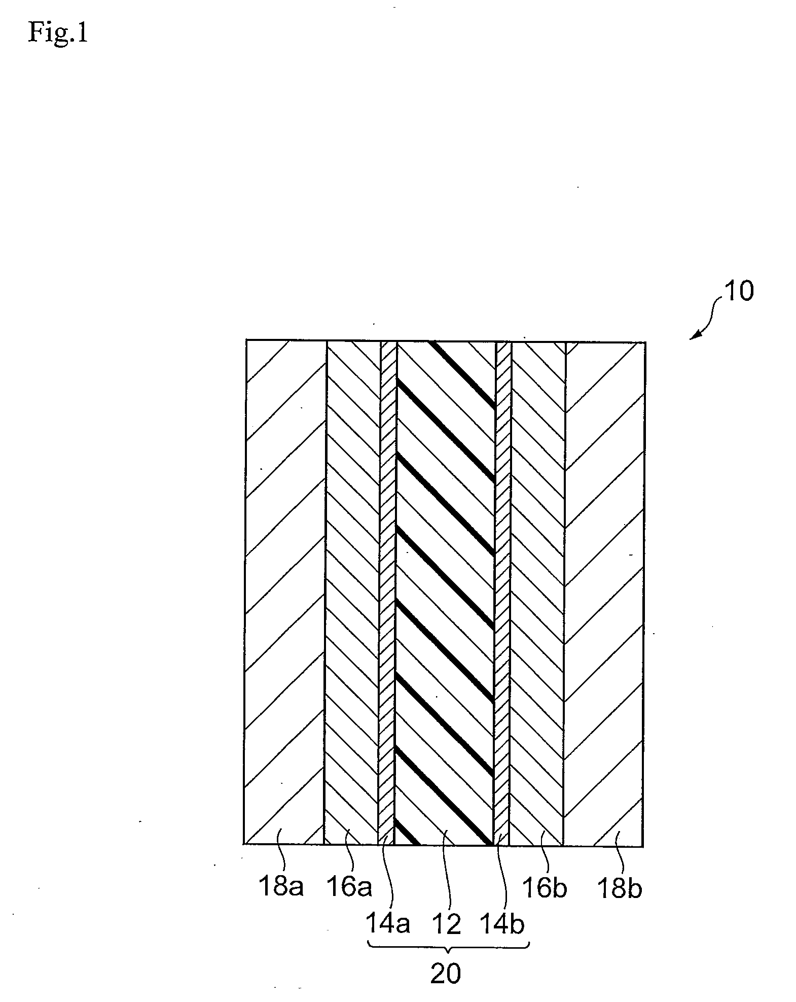
Image

Examples
example 1
[Example 1
Production and Evaluation of Fuel Cell]
(Preparation of Catalyst Ink A)
[0163]First, the catalyst inks necessary for production of the membrane-electrode assembly were prepared. Specifically, 1.00 g of platinum-supporting carbon with platinum supported at 51 wt % was loaded into 6 mL of commercially available 5 wt % Nafion solution (polymer electrolyte solution, solvent: mixture of water and lower alcohol), and then 13.2 mL of ethanol was added and 3.77 g of aromatic polymer emulsion A obtained as described above was added. The obtained mixture was subjected to ultrasonic treatment for 1 hour and then stirred for 5 hours with a stirrer to obtain catalyst ink A.
[0164](Production of Membrane-Electrode Assembly)
[0165]Catalyst ink A was coated by spraying onto a 5.2 cm-square region at the center of one side of polymer electrolyte membrane 1 obtained by the production method described above. The distance was 6 cm from the discharge slit to the membrane, and the stage temperature...
example 2
(Preparation of Catalyst Ink B)
[0174]After loading 1.00 g of platinum-supporting carbon with platinum supported at 51 wt % into 6 mL of a 5 wt % Nafion solution (polymer electrolyte solution, solvent: mixture of water and lower alcohol), 13.2 mL of ethanol was added and 5.00 g of aromatic polymer emulsion B obtained as described above was added. The obtained mixture was subjected to ultrasonic treatment for 1 hour and then stirred for 5 hours with a stirrer to obtain catalyst ink B.
[0175](Production of Membrane-Electrode Assembly)
[0176]Membrane-electrode assembly 2 was fabricated in the same manner as Example 1, except that catalyst ink B was used instead of catalyst ink A. The anode catalyst layer and cathode catalyst layer of the membrane-electrode assembly 2 were layers comprising 0.6 mg / cm2 platinum as calculated from the compositions and coated weights.
[0177](Production of Fuel Cell)
[0178]A fuel cell was fabricated by the same method as Example 1, except for using membrane-elec...
example 3
(Production of Membrane-Electrode Assembly)
[0179]Membrane-electrode assembly 3 was fabricated by the same method as Example 1, except for using polymer electrolyte membrane 2 instead of polymer electrolyte membrane 1. The anode catalyst layer and cathode catalyst layer of the membrane-electrode assembly 3 were layers comprising 0.6 mg / cm2 platinum as calculated from the compositions and coated weights.
[0180](Production of Fuel Cell)
[0181]A fuel cell was fabricated by the same method as Example 1, except for using membrane-electrode assembly 3. The obtained fuel cell was subjected to a load change test and the characteristics of the fuel cell were evaluated, in the same manner as Example 1.
PUM
| Property | Measurement | Unit |
|---|---|---|
| Acidity | aaaaa | aaaaa |
| Durability | aaaaa | aaaaa |
Abstract
Description
Claims
Application Information
PatSnap Eureka turns technology decisions into work you can execute. Powered by our Innovation Knowledge Graph, it runs expert workflows across engineering, life sciences, materials and intellectual property. Get your review-ready output in minutes.


