Piezoelectric devices and methods for manufacturing same

a technology of piezoelectric devices and manufacturing methods, which is applied in the direction of device details, piezoelectric/electrostrictive device details, generators/motors, etc., can solve the adverse effects of remaining metal on the oscillating characteristics of the piezoelectric vibrating piece, corrode the electrodes, consume valuable manufacturing time, etc., to prevent the effect of corroding the electrode, reducing the manufacturing steps for forming frequency adjustment holes and electrode through-hol

Inactive Publication Date: 2010-08-12
NIHON DEMPA KOGYO CO LTD
View PDF11 Cites 39 Cited by
  • Summary
  • Abstract
  • Description
  • Claims
  • Application Information

AI Technical Summary

Benefits of technology

[0020]In some embodiments the transverse section (“diameter”) of each frequency-adjustment hole progressively decreases with distance, in the thickness dimension, from the outer major surface to the inner major surface of the lid. This configuration, desirably achieved by machine processing, effectively prevents incursion of molten sealing material (eutectic metal) into the interior of the piezoelectric device, allowing for reliable sealing being performed during a sealing step.
[0021]In some embodiments each electrode through-hole has a first portion and a second portion that meet at a connecting point in the thickness dimension of the package base. In the first portion, desirably formed by machine processing, the transverse section (“diameter”) progressively decreases with distance, in the thickness dimension, from the outer major surface to the connecting point. In the second portion, desirably formed by wet etching, the transverse section progressively decreases with distance, in the thickness dimension, from the inner major surface to the connecting point. This configuration prevents molten sealing material (eutectic metal) from flowing into the interior of the piezoelectric device.
[0022]After adjusting the vibration frequency of the vibrating arms using a laser beam illuminated through the frequency-adjustment holes, the interior of the piezoelectric device desirably is evacuated by application of vacuum, which evacuates the interior of the device via the frequency-adjustment holes. Thus, the vibration frequency is adj...

Problems solved by technology

This residual moisture or gas tends to corrode the electrodes and/or cause an adverse effect on the oscillating characteristics of the piezoelectric vibrating piece.
Such a step consumes valuable manufacturing time and decreases manufacturing efficiency.
If, in an effort to eliminate the temperature-change step to improve efficiency, the anodic bonding were conducted at the higher temperature, the different coefficients of thermal expansion of the crystal material of the piezoelectric vibrating piece and of the glass material of the lid and package base would cause fracture of the piezoelectric devices.
Although the through-holes of piezoelectric devices discussed in the JP '238 reference are sealed, on an asse...

Method used


Image

  • Piezoelectric devices and methods for manufacturing same
  • Piezoelectric devices and methods for manufacturing same
  • Piezoelectric devices and methods for manufacturing same

Examples


first embodiment

of Piezoelectric Vibrating Device

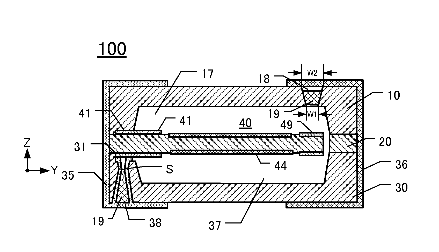
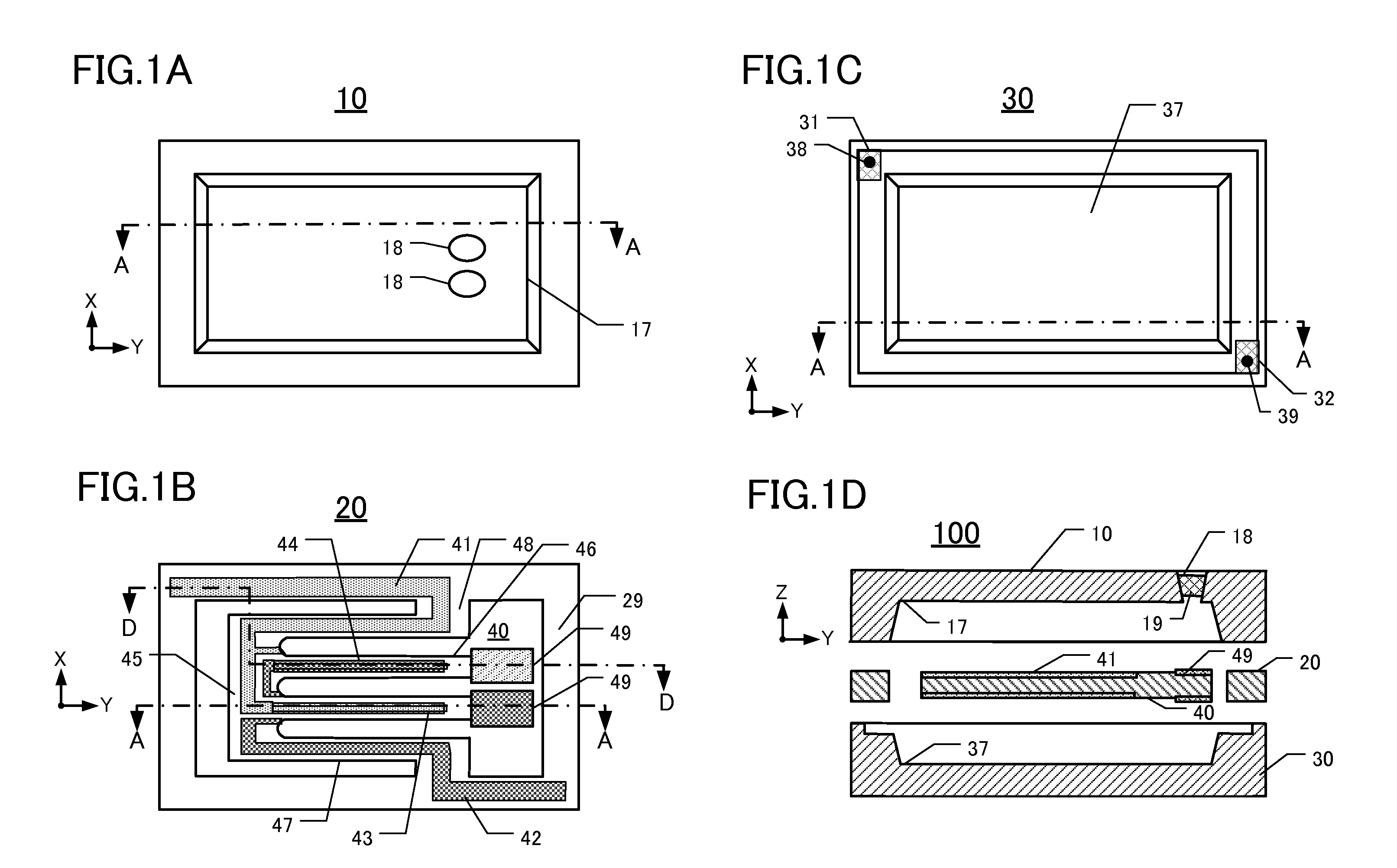
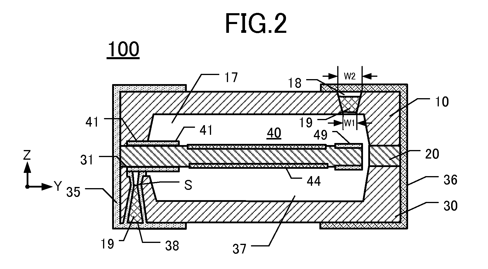
[0035]Relevant details of this embodiment of a piezoelectric vibrating device 100 are depicted in FIGS. 1A-1D. FIG. 1A is a plan view of the inner major surface of a lid 10 of the device 100. FIG. 1B is a plan view of the upper major surface of a “piezoelectric frame”20 including a piezoelectric vibrating piece 40. FIG. 1C is a plan view of the inner major surface of a package base 30 of the device 100. FIG. 1D is an elevational section along the line A-A of FIGS. 1A-1C. Note that the “piezoelectric vibrating device” of this embodiment comprises the piezoelectric frame 20 (including the piezoelectric vibrating piece 40) sandwiched between the lid 10 and package base 30. Thus, the lid 10, frame 20, and package base 30 collectively form a “package” enclosing the piezoelectric vibrating piece 40 in a space inside the package. To facilitate comprehension of relevant details, a first external electrode 35 and a second external electrode 36 (see FIG. 2) ar...

second embodiment

of Piezoelectric Vibrating Device

[0065]This embodiment 200 is shown in FIG. 4, which is a simplified elevational section of the subject piezoelectric vibrating device. Only the differences from the first embodiment 100 are described below. The second embodiment 200 has almost the same configuration as the first embodiment 100, except that, in the second embodiment the elevational sectional profile of the frequency-adjustment holes 18b is similar to the elevational sectional profile of the electrode through-hole 38. I.e., the diameter of the frequency-adjustment hole 18b progressively narrows with increased depth from both major surfaces. The progressions change at the connecting point H.

[0066]As the frequency-adjustment holes 18b are being formed, a first portion of each hole formed by machine processing (e.g., sand-blasting) from the outer major surface of the lid 10 into the thickness dimension of the lid. Machining is stopped at the connecting point H to avoid having the machined...


PUM

PropertyMeasurementUnit
Thicknessaaaaaaaaaa
Electrical conductivityaaaaaaaaaa
Diameteraaaaaaaaaa

Abstract

An exemplary piezoelectric vibrating device includes a piezoelectric frame that supports and surrounds a tuning-fork type piezoelectric vibrating piece having a pair of vibrating arms. The device also includes a lid and a package base that are siloxane-bonded to the frame. The lid defines at least one frequency-adjustment hole extending through the thickness dimension of the lid from an inner major surface thereof (facing the frame) to an outer major surface of the lid. The package base defines at least one through-hole electrode passing via a respective electrode through-hole through the thickness of the base from an inner major surface thereof (facing the frame) to the outer major surface thereof. The electrode is connected to the piezoelectric vibrating piece. The lid and base include external electrodes, made of an electrically conductive material, that cover the through-holes and frequency-adjustment hole(s).

Description

CROSS-REFERENCE TO RELATED APPLICATION[0001]This application claims priority to and the benefit of Japan Patent Application No. 2009-028144, filed on Feb. 10, 2009, in the Japan Patent Office, the disclosure of which is incorporated herein by reference in its entirety.FIELD[0002]This disclosure pertains to, inter alia, piezoelectric devices comprising a tuning-fork type piezoelectric vibrating piece enclosed in a package.DESCRIPTION OF THE RELATED ART[0003]Various types of clocks, home electric appliances, and consumer electronics, and various types of commercial / industrial electrical apparatus such as Office-Automation (OA) devices utilize at least one oscillator. These oscillators typically are manufactured by packaging a piezoelectric resonator, a piezoelectric vibrating device, or an IC chip as a clock source for addition to and use by an electronic circuit of the apparatus. In other apparatus, piezoelectric timing devices such as real-time clock modules are widely used.[0004]A ...

Claims


Application Information

Patent Timeline
IPC IPC(8): H01L41/053H01L41/04H01L41/22H03H3/04H03H9/02
CPCH03H3/04H03H9/1035Y10T29/42H03H2003/0492H03H9/21
Inventor INOUE, TAKAHIROSAITO, TAKEFUMIUMEKI, MITOSHIICHIKAWA, RYOICHI
Owner NIHON DEMPA KOGYO CO LTD
Why Eureka
Try Eureka