Projector

a projector and projection image technology, applied in the field of projectors, can solve the problems of inability to detect inner distortion of the projected image, inability to support inability to appropriately correct the projection image with the conventional correction method, so as to suppress the deterioration of the image quality of the main image and the simple configuration

Active Publication Date: 2010-08-12
PANASONIC CORP
View PDF10 Cites 124 Cited by
  • Summary
  • Abstract
  • Description
  • Claims
  • Application Information

AI Technical Summary

Benefits of technology

[0015]It is an object of the present invention to provide a projector that has a simple configuration and can insert an image for co

Problems solved by technology

This means that appropriate correction is not possible with the conventional correction method for a projection image, that is based on the assumption that the relative positions of the projector and screen are fixed.
This method of correcting the four corners of the image, however, is based on the assumption that the image is basically projected onto a flat screen, so the inner distortion of the projected image cannot be detected.
In some cases, a projection may be performed on a curved surface or a three-dimensional object having bumps on the surface, which a conventional correction method cannot support.
In this case, a dramatic deterioration of image quality is inevitable since the test pattern images are superimposed on an originally observed im

Method used


Image

  • Projector
  • Projector
  • Projector

Examples


embodiment 1

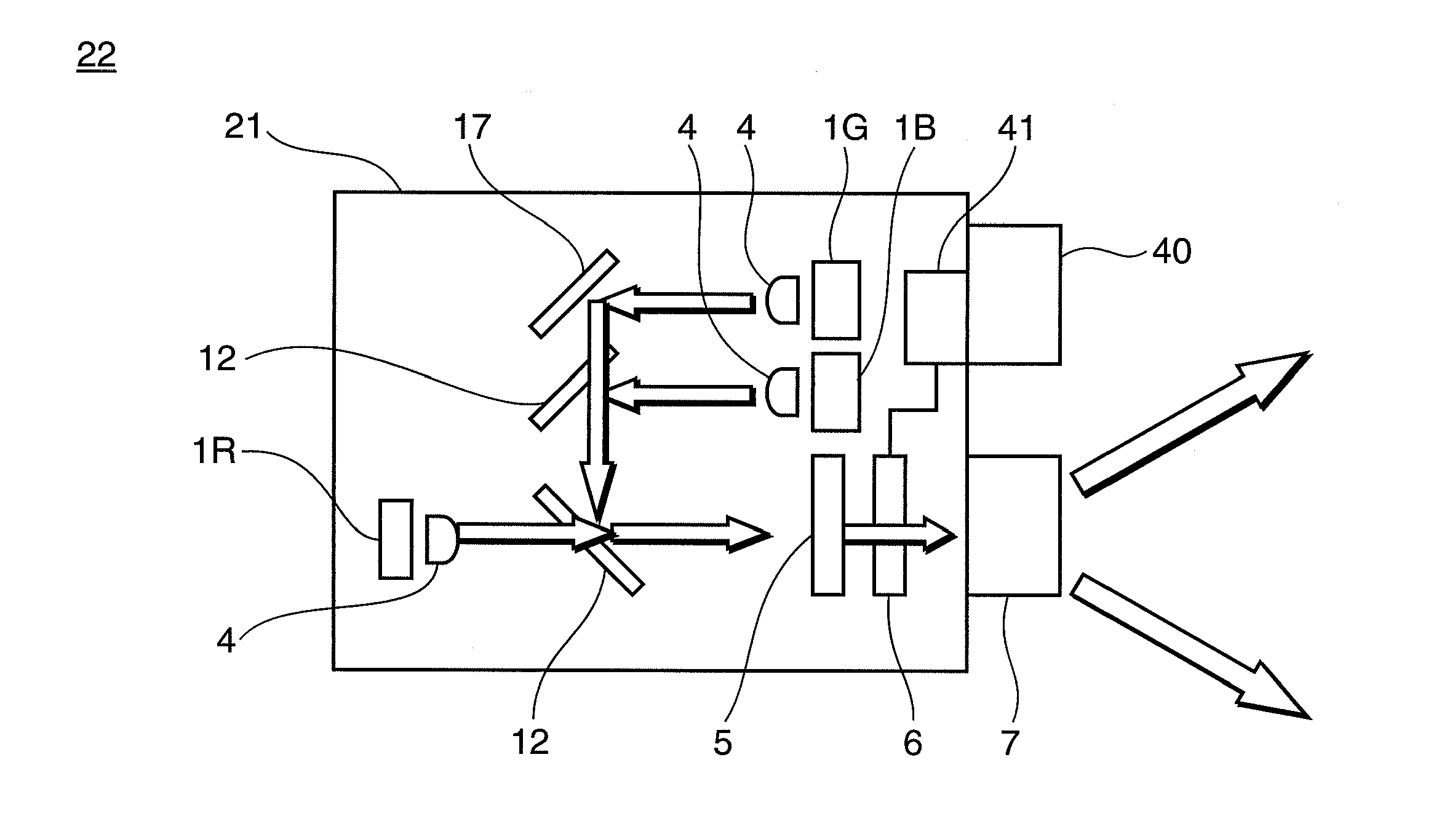
[0052]A projector according to Embodiment 1 of the present invention will now be described with reference to FIG. 1 to FIG. 7.

[0053]FIG. 1 shows a general configuration of the projector 22 according to Embodiment 1 of the present invention.

[0054]As FIG. 1 shows, the present projector 22 has a laser light source 1R, laser light source 1G and laser light source 1B for each color, collimator lenses 4, lenticular lens 5, spatial modulation element 6, projection lens 7 and dichroic mirrors 12. From the laser light sources 1R, 1G and 1B, red, blue and green laser lights are emitted sequentially. The green laser light becomes substantially parallel light by the collimator lens 4, and then is reflected by a mirror 17, and transmits through the dichroic mirror 12. The blue laser light becomes approximately parallel light by the collimator lens 4, and then is multiplexed with the green laser light by the dichroic mirror 12. The red laser light becomes substantially parallel light by the colli...

embodiment 2

[0089]A projector according to Embodiment 2 of the present invention will now be described with reference to FIG. 8 to FIG. 11.

[0090]The basic configuration of the projector 90 according to the present embodiment is the same as the projector 22 according to Embodiment 1 shown in FIG. 1, so composing elements are denoted with same reference symbols, and detailed description thereof is omitted.

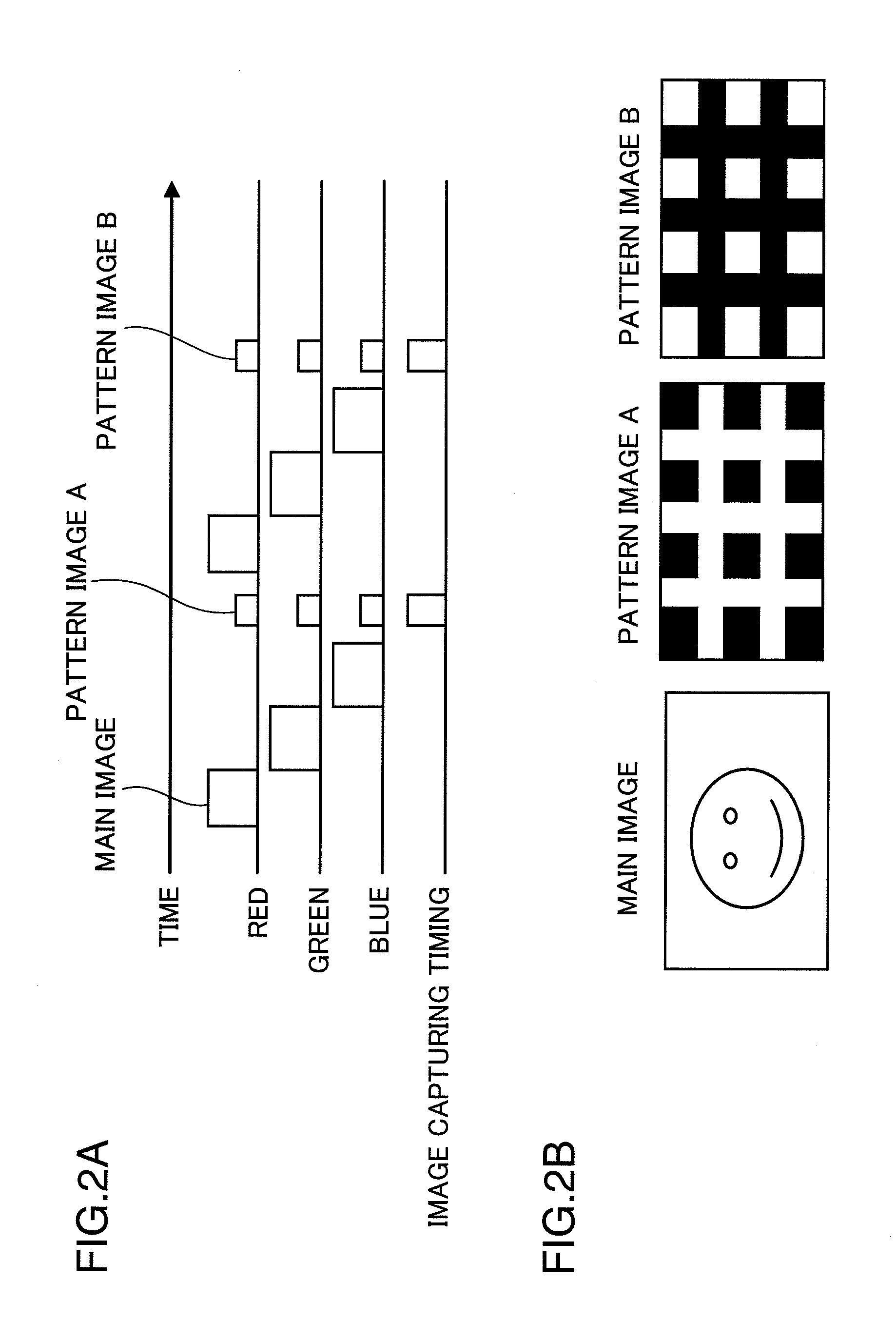
[0091]In the present embodiment, a uniform image is used for the correction image, instead of the lattice pattern image of Embodiment 1.

[0092]FIG. 8 shows a timing to project uniform image A as the correction image of the present embodiment, and a timing for the imaging element 40 to capture the uniform image A.

[0093]Uniform image A is an image of which brightness is uniform, generated by light in which a red laser light, green laser light and blue laser light are superimposed. The laser output power ratio of the red laser light source 1R, green laser light source 1G and blue laser light source ...

embodiment 3

[0103]A projector according to Embodiment 3 of the present invention will now be described with reference to FIG. 12 and FIG. 13.

[0104]The basic configuration of each projector according to the present embodiment is the same as the projector 22 according to Embodiment 1 in FIG. 1. Therefore composing elements the same as Embodiment 1 are denoted with the same reference symbols, for which detailed description is omitted.

[0105]In the present embodiment as well, if the image, other than the main image, is time-integrated based on control of the image correction controller (display control unit) 41 shown in FIG. 1, the correction image signal for projecting the correction image, that is visually recognized as a uniform white or gray screen, is inserted between cyclic main image signals, but in the present embodiment, this correction image is a two-dimensional code image, which can include various information. In other words, the difference of the present embodiment from the above mentio...


PUM


Abstract

A projector has: light source (1R, 1G, 1B); a light modulation unit (6) that modulates a light emitted from the light source based on image signals; a display control unit (41) that outputs the image signals including main cyclic image signals to the light modulation unit, and controls the display thereof; a projection unit (7) that projects the image based on the light modulated by the light modulation unit; and an imaging unit (40) that captures an image to be displayed based on the light projected from the projection unit, and the display control unit inserts a correction image signal for projecting a correction image, which is visually recognized as a uniform white or gray screen when time integration is performed, between the cyclic main image signals.

Description

TECHNICAL FIELD[0001]The present invention relates to a projector that projects an image on a projection target.BACKGROUND ART[0002]Recently compactness with good portability is demanded for projectors, and even pocket sized projectors, which can be carried around in a pocket, have been the subject of research and development. As such downsizing progresses, downsizing of an optical system of projectors, constituted by a light source, spatial modulation element and projection optical system, using an LED (Light Emitting Diode) or laser, instead of a lamp, is also under consideration.[0003]A pocket sized compact projector can always be carried around, and the way of use is dramatically different from conventional stationary projectors. Such a compact project has good portability, and a user can use the projector that is hand held to project onto a nearby wall and / or object in order to view an image thereof. This pocket sized compact projector can be used even during movement, such as ...

Claims


Application Information

Patent Timeline
IPC IPC(8): H04N3/26G03B21/00G09G3/02G09G3/20G09G3/34G09G5/00H04N5/74H04N9/31
CPCG03B21/00G09G3/3433H04N9/3129H04N9/3197H04N9/3173H04N9/3185H04N9/3194H04N9/3164G03B21/005
Inventor NAKAYAMA, KENJIITOH, TATSUOFURUYA, HIROYUKIKADOWAKI, SHINICHIYAMAMOTO, KAZUHISA
Owner PANASONIC CORP
Why Eureka
Try Eureka