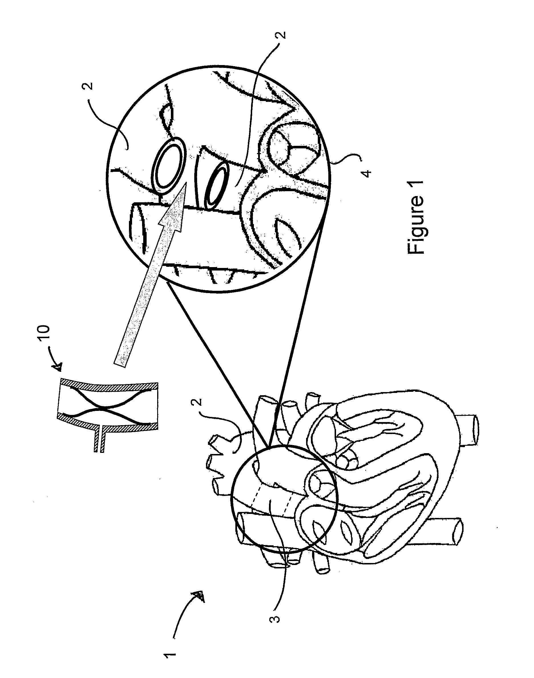
[0008]Thus, the outflow from the native heart may be augmented through the use of the blood pump of the present invention. The blood pump is surgically placed interpositionally within the
aorta (i.e. the blood pump is implanted into the
aorta by end-to-end
anastomosis to replace a resected portion of the
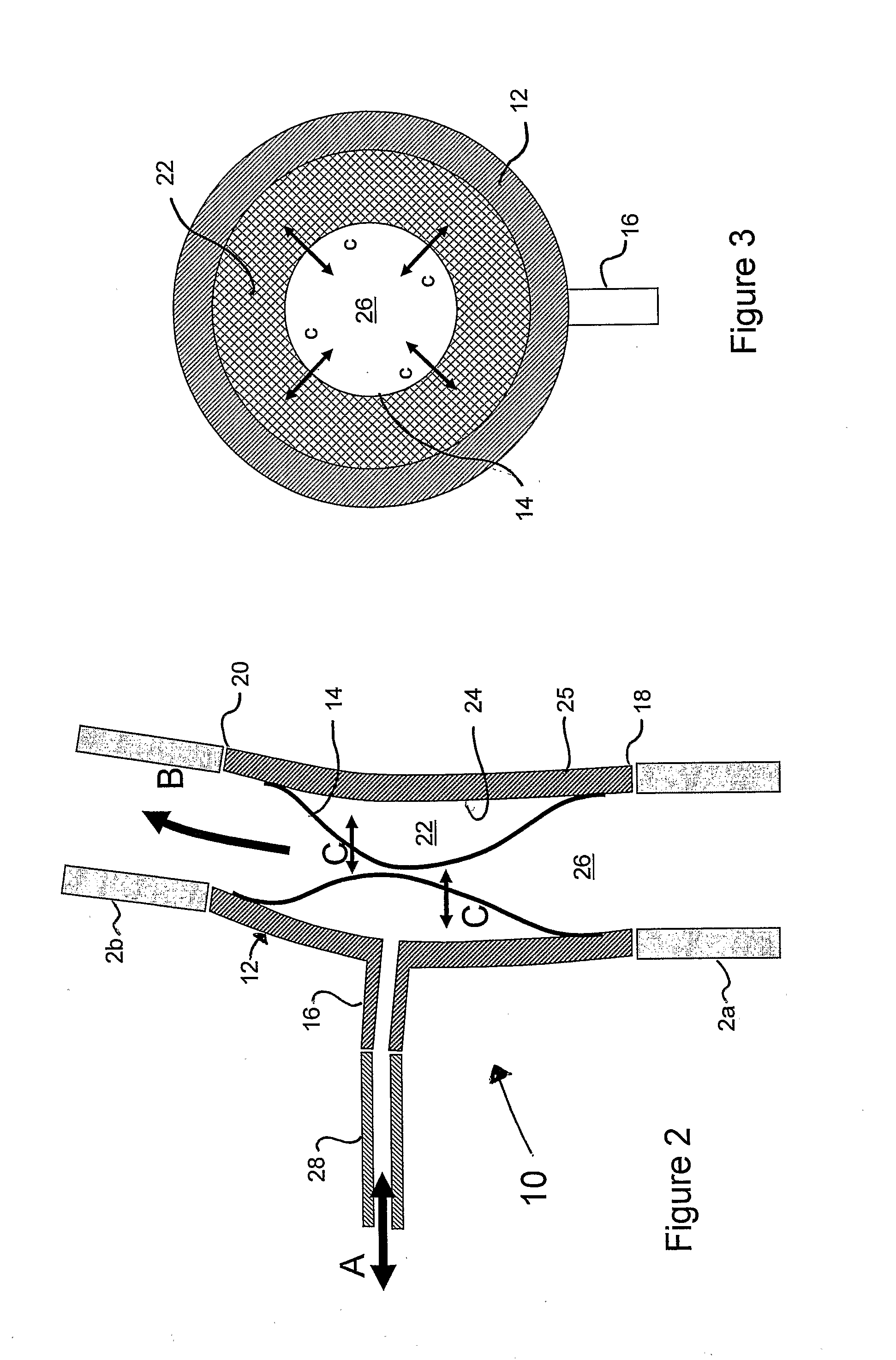
aorta). The cross-sectional area of the blood passageway through the blood pump is caused to contract due to the flow of fluid into and out of the fluid chamber between the tubular body and the flexible membrane of the blood pump. The blood pump may be used in the temporary or long-term treatment of patients suffering heart failure through intermittent or temporary
continuous use when counter-pulsed with the natural heart. Additional embodiments can also be contemplated so as to reduce the
workload required from the native heart, to augment coronary
artery perfusion, and / or to treat other circulatory diseases by introducing such a blood pump into the
peripheral circulation.
[0011]The second group of patients for whom the present invention would be particularly beneficial are patients needing long term chronic support. This group of patients will never recover cardiac function and will be maintained on medical therapies in the long term. The “healthier” of these are minimally supported with medical therapies but require more aggressive support intermittently; typically such patients would be admitted to hospital for one or two weeks respite and receive low doses of inotropes and diuretics which is sufficient to reduce ventricular overload, to restore end
organ function and to promote a feeling of well being. Patients receiving more aggressive medical therapies need additional support in times of crisis and would be admitted to
intensive care and aided with an IABP such as those of U.S. Pat. No. 6,210,318 and EP0192574. Patients with the worst prognosis may well find themselves on the heart transplant
list. A small number of these patients will suffer failing health whilst on the transplant
list and will need mechanical assist to bridge them to
transplantation. The present invention promises to be a useful
treatment modality in each of these scenarios. For the “healthier” patients, treatment may be augmented with the blood pump of the present invention, in addition to
medical therapy to provide respite. Once installed, and for subsequent readmission, use of the present blood pump can be very quickly effected and will be fast acting. For patients on higher doses of medication in crisis, the present invention will allow speedier deployment and will allow the patient to be
ambulatory and reduce the
risk of infection posed by IABPs, as described further below. The present invention will greatly reduce the cost of bridge-to-
transplantation by removing the need for an implanted VAD or the need for
intensive care beds that would have been required if an external VAD were used.
[0018]The tubular body may be rigid or may be flexible. Advantageously, the tubular body comprises a flexible material. More advantageously, the tubular body comprises one or more non-stretch elements for preventing the tubular body from distending significantly when fluid flows into the fluid chamber. For example, the non-stretch elements may be non-stretch filaments having a spiral, axial or annular configuration with respect to the tubular body.
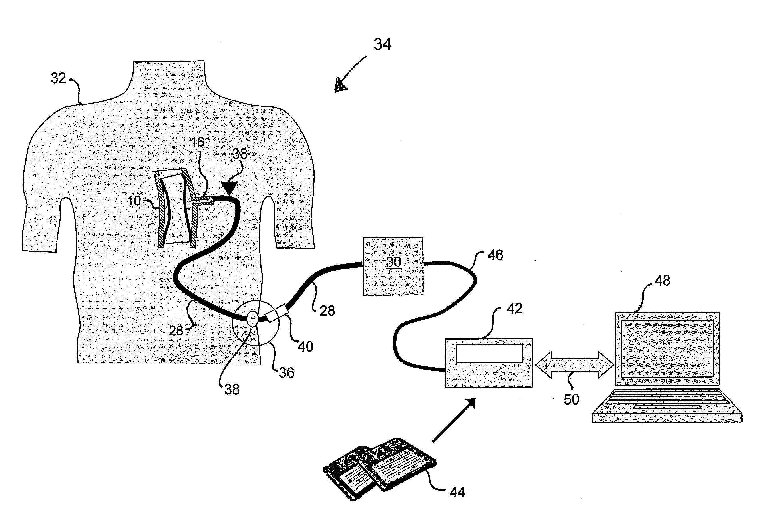
[0026]According to a third aspect of the present invention, there is provided a method for the treatment of heart failure in a patient. The method comprises: resecting a portion of a
blood vessel of the patient; anastomosing a pulsatile blood pump of the first aspect into the resected
blood vessel; providing a fluid conduit which extends percutaneously out of the patient from the port of the blood pump; and driving fluid along the fluid conduit alternately into and out of the fluid chamber of the blood pump, thereby enabling the blood pump to
pump blood along the blood passageway.
[0032]According to a fourth aspect of the present invention, there is provided a method for augmenting the
perfusion of a patient's limbs and / or organs and / or tissue. The method comprises: resecting a portion of a
peripheral blood vessel of the patient; anastomosing a pulsatile blood pump of the first aspect into the resected blood vessel; providing a fluid conduit which extends percutaneously out of the patient from the port of the blood pump; and driving fluid along the fluid conduit alternately into and out of the fluid chamber of the blood pump, thereby enabling the blood pump to
pump blood along the blood passageway.

