Bypass engine with contrarotating turbine wheels

a technology of turbine wheels and bypass engines, which is applied in the direction of machines/engines, efficient propulsion technologies, mechanical equipment, etc., can solve the problems of reducing the operation of the turbine, reducing the overall mass of the engine, and rotating the fan at the same speed of rotation as the low-pressure turbine, so as to reduce the mechanical stress, the effect of reducing the size of the disk and reducing the mechanical load

Active Publication Date: 2010-08-19
SN DETUDE & DE CONSTR DE MOTEURS DAVIATION S N E C M A
View PDF28 Cites 41 Cited by
  • Summary
  • Abstract
  • Description
  • Claims
  • Application Information

AI Technical Summary

Benefits of technology

[0009]Said LP turbine operates like a conventional turbine in which the stator is fixed and in which the speed of rotation of the rotor is equal to the sum of the speeds of rotation of the two movable wheels. However, since the speeds of rotation of these two bladed wheels are small by comparison with that of the rotor of a conventional turbine, there is obtained a high reduction in the mechanical stresses associated with,

Problems solved by technology

This configuration has the disadvantage of rotating the fan at the same speed of rotation as the low-pressure turbine.
However, slowing down the speed of rotation of the low-pressure shaft results in a degradation of the operation of the turbine which, itself, by contrast, needs to rotate quickly in order to have a good efficiency and to help achieve a

Method used


Image

  • Bypass engine with contrarotating turbine wheels
  • Bypass engine with contrarotating turbine wheels
  • Bypass engine with contrarotating turbine wheels

Examples


first embodiment

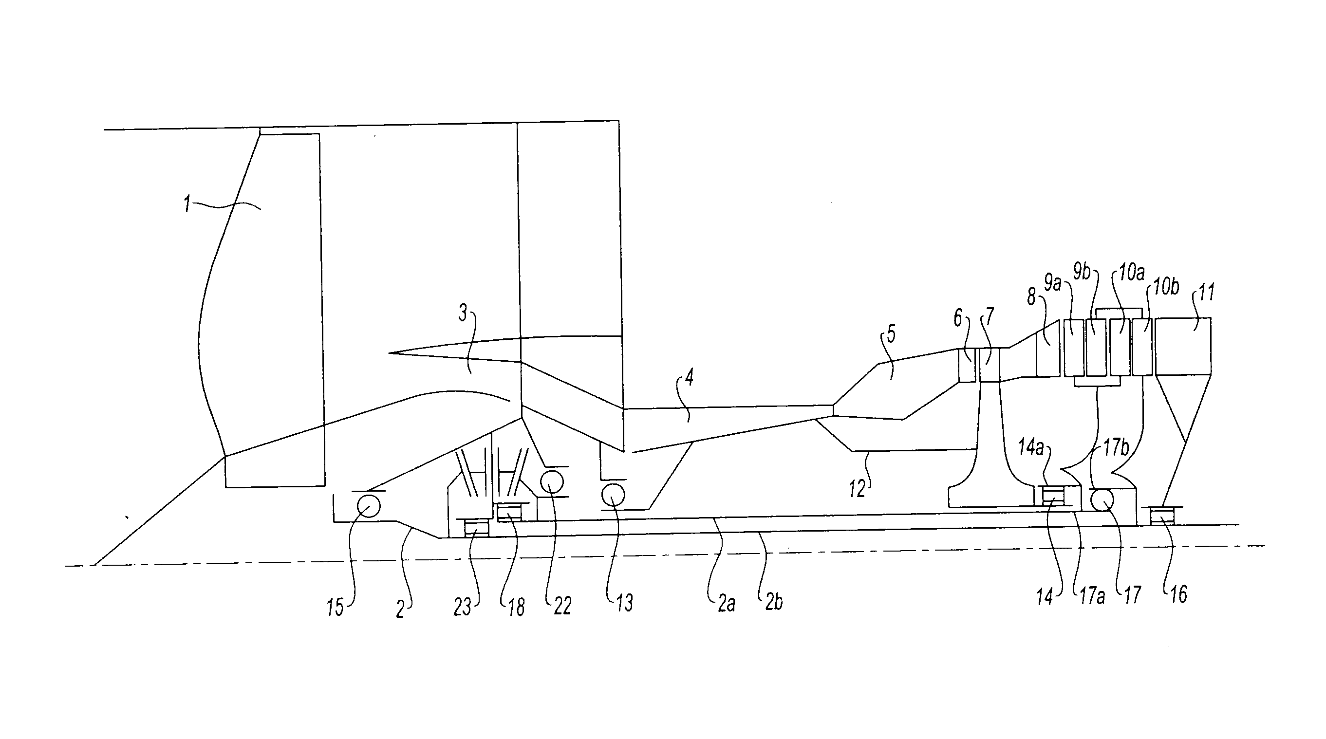
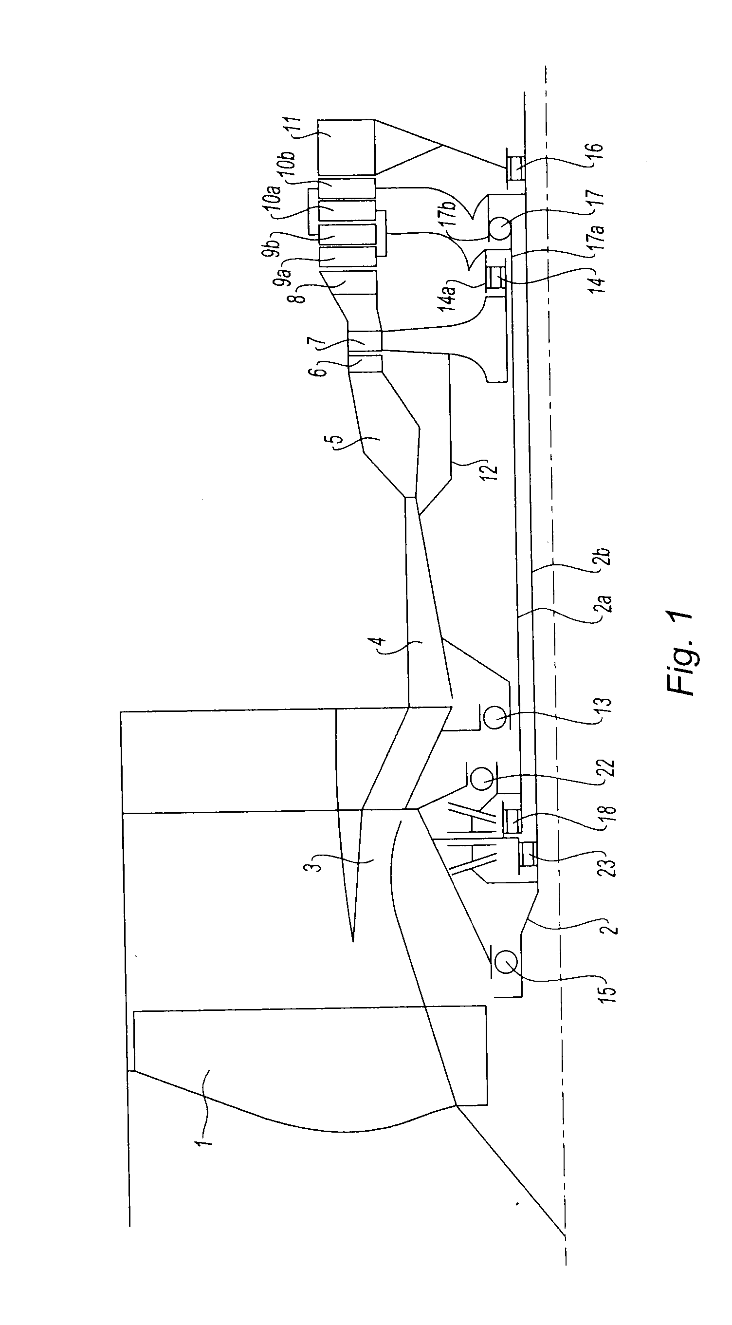
[0028]Each of the stages of the LP turbine comprises, in the first embodiment, a wheel 9a, 10a, analogous to a stator wheel, called first wheels here, and a wheel analogous to a rotor wheel 9b, 10b, called second wheels here. All these blades are able to rotate, unlike the prior art where the blades of stator type are fixed. The second wheels 9b and 10b of the two stages are conventionally connected to a second turbine shaft 2b, which passes longitudinally through the engine and which forms, at its front end, the LP shaft 2 driving the fan 1. The first wheels 9a and 10a of the two stages are mounted on a first LP turbine shaft 2a, which can rotate like the LP shaft 2b, but in the opposite direction.

[0029]The second wheels of the two stages, which are connected to the second turbine shaft 2b, are carried by a bearing unit 17b which co-operates with an LP turbine inter-shaft ball bearing 17, while the first wheels of the two stages are connected to the first turbine shaft 2a and carri...

second embodiment

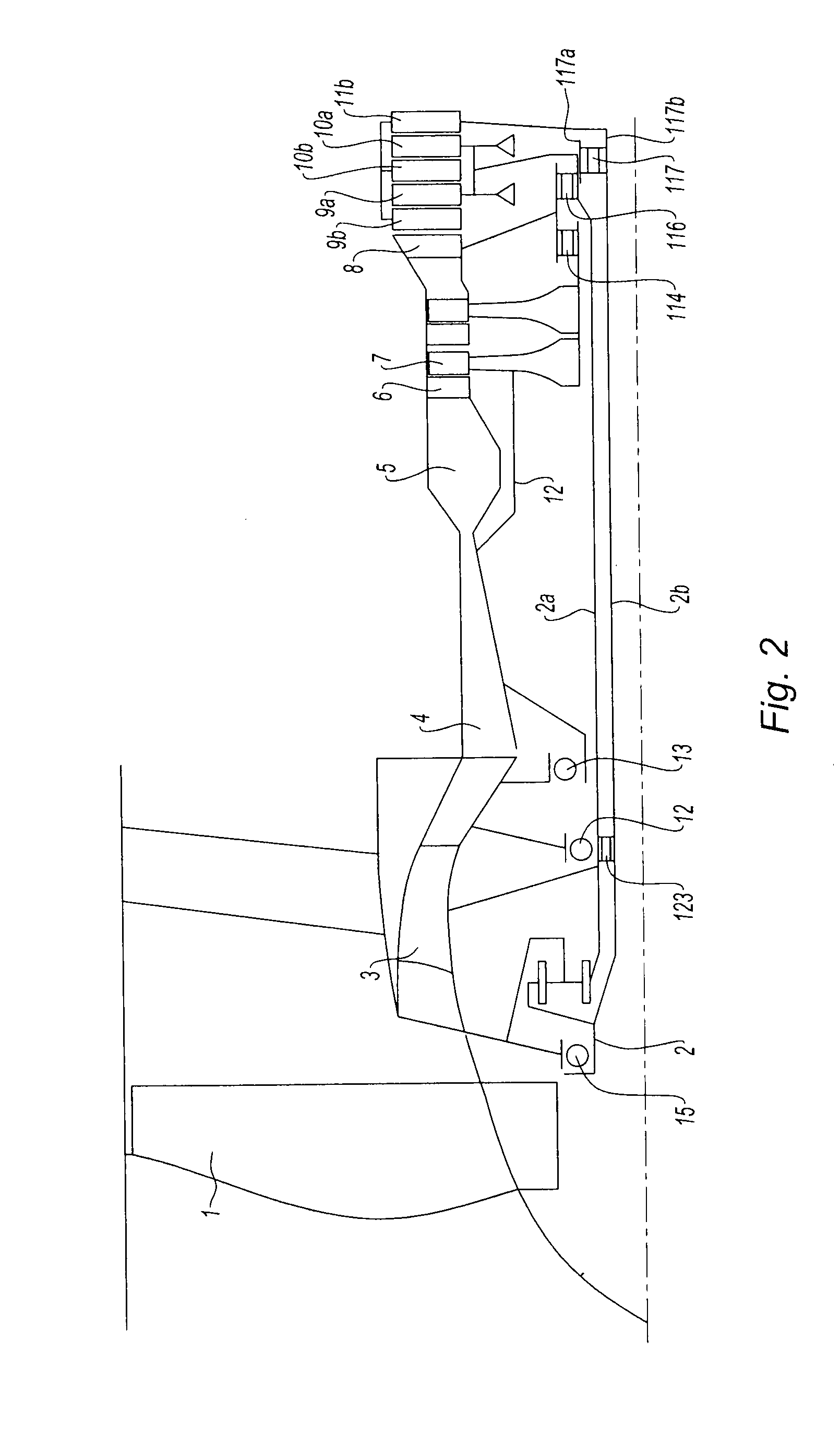
[0035]In a variant described schematically by FIG. 5 and illustrated in FIG. 2 with the second embodiment, the reversing module is composed of two spur pinions 19 and 21 which are concentric with the axis of the engine, and which mesh with one or more reversing spur pinions 20. As previously, the first pinion 19 is mounted in a sliding manner on the first LP shaft 2a via splines, while the second pinion 21 is mounted in a sliding manner on the second LP shaft 2b via splines. The reversing pinions 20 turn on shafts kept in place by the structure of the engine. This variant is adapted in the case of an engine in which the two LP turbine shafts 2a and 2b rotate at different speeds.

[0036]With reference now to FIG. 2, there can be seen a second embodiment of the invention. The references of the identical parts in the two embodiments are retained; the parts having a function analogous to those of the first embodiment are designated by the same reference, incremented by 100.

[0037]The upstr...


PUM


Abstract

Bypass aeronautical engine comprising a fan (1), an LP compressor (3) and an HP compressor (4), a combustion chamber (5), an HP turbine and at least one LP turbine stage, said LP stage comprising a first movable bladed wheel (9a, 10a) carried by a first turbine shaft and a second movable bladed wheel (9b, 10b, 11b) turning in the opposite direction to said first wheel, said fan being driven by said second wheel via a second turbine shaft (2b) and by said first shaft (2a) via a module for reversing its direction of rotation, wherein the reversing module is produced with the aid of two bevel pinions (19, 21) of the same size, carried respectively by the first and second LP turbine shafts, and with the aid of a reversing pinion (20), the two turbine shafts (2a, 2b) turning in absolute value at the same speed of rotation.

Description

[0001]The field of the present invention is that of turbomachines, and in particular turbofans or bypass jet engines, for aeronautics.BACKGROUND OF THE INVENTION AND DESCRIPTION OF THE PRIOR ART[0002]The designers of aeronautical engines for commercial aircraft are constantly seeking to reduce the mass, the specific consumption of their projects, that is to say the consumption expressed in kg of fuel consumed per kg of created thrust, and the level of noise which they generate in use. To that end, the engine most used at the current time is the turbofan which consists of a twin-spool bypass engine with a high bypass ratio, with a fan of large diameter which is driven directly by the low-pressure turbine.[0003]This configuration has the disadvantage of rotating the fan at the same speed of rotation as the low-pressure turbine. Now, in order to obtain good specific consumptions and a reduced noise level, this fan should be rotated as slowly as possible while adapting the profile of th...

Claims


Application Information

Patent Timeline
IPC IPC(8): F02K3/00
CPCF01D1/24F02C3/067F05D2260/4031F02K3/072Y02T50/671F02C3/107Y02T50/60F01D5/03
Inventor GALLET, FRANCOIS
Owner SN DETUDE & DE CONSTR DE MOTEURS DAVIATION S N E C M A
Why Eureka
Try Eureka