

Liquid crystal display panel and liquid crystal display device
- Summary
- Abstract
- Description
- Claims
- Application Information
AI Technical Summary
Benefits of technology
Problems solved by technology
Method used
Image

Examples
embodiment 1
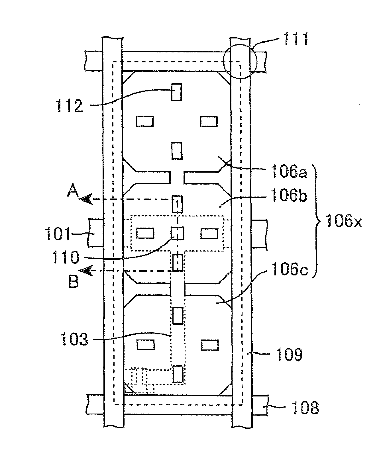
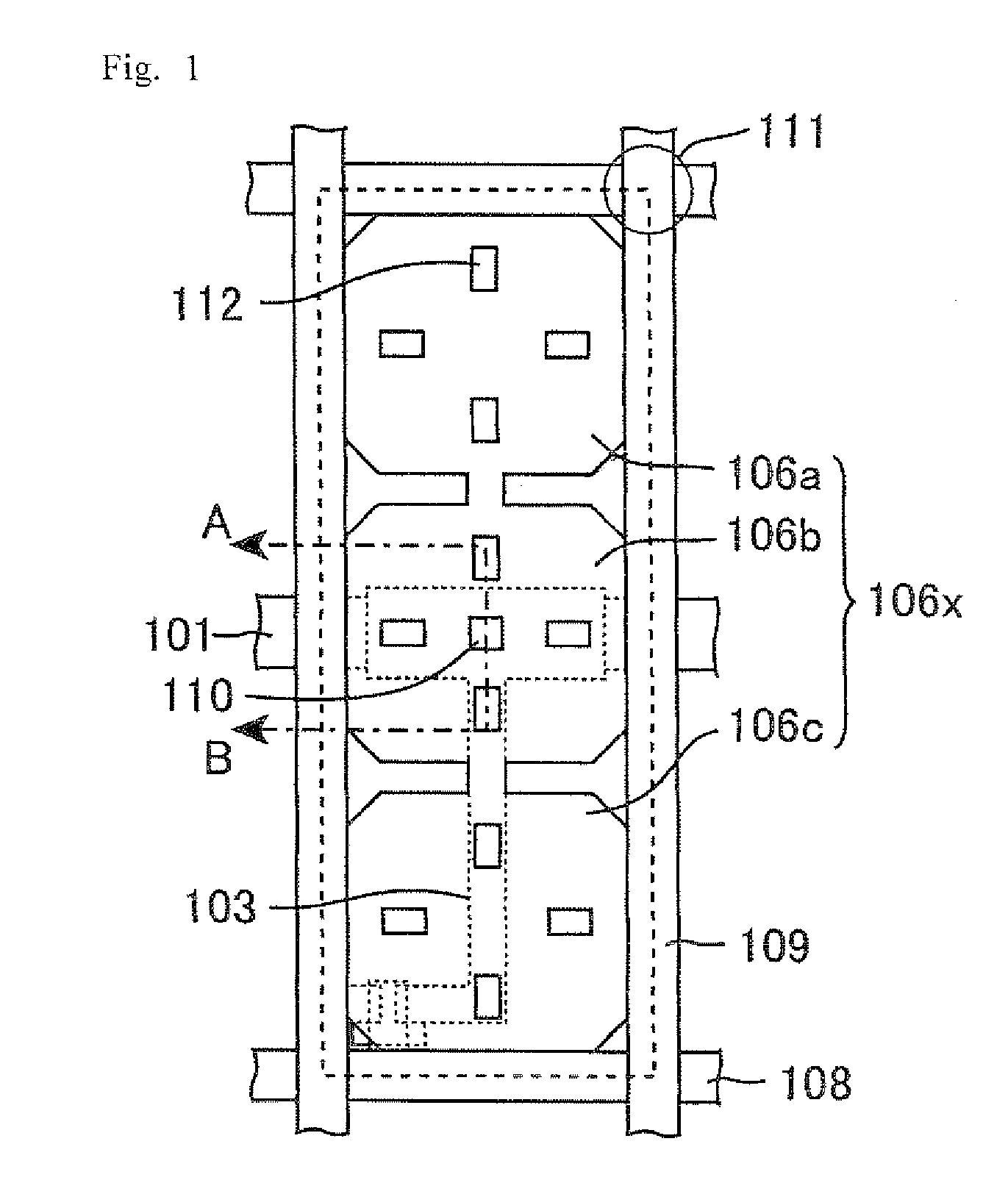
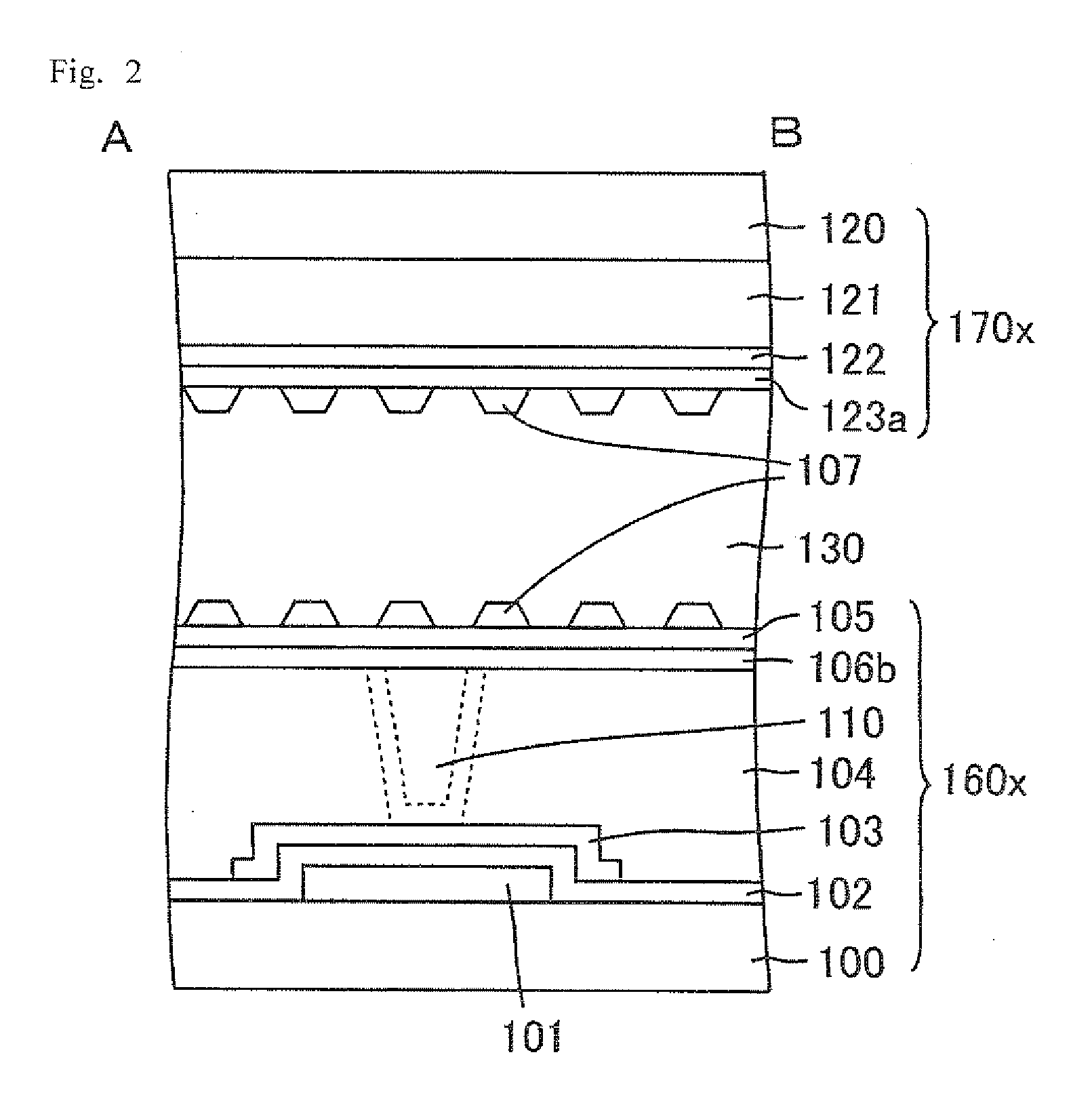
[0073]FIG. 1 is a plan view schematically showing a configuration of one pixel of an LCD panel in accordance with Embodiment 1. FIG. 2 is a schematic cross-sectional view taken along line A-B of FIG. 1.
[0074]As shown in FIGS. 1 and 2, three sub-pixel electrodes 106a, 106b, and 106c are formed in one pixel region surrounded by gate wirings 108 and source wirings 109, which are arranged to be perpendicular to each other, in a back-side substrate 160x of the LCD panel in accordance with Embodiment 1. The sub-pixel electrodes 106a, 106b, and 106c are arranged so that the long side of the pixel electrode 106x is divided into three. Between each of adjacent ones of the sub-pixel electrodes 106a to 106c, a region free from an electrode is arranged. Liquid crystal molecules can be aligned in a pinwheel pattern at an edge of each of the sub-pixel electrodes 106a to 106c. In each of the sub-pixel electrodes 106a to 106c, two openings 112 are arranged toward the center of the corresponding ele...
PUM
 Abstract
Description
Claims
Application Information