Dual-stage switching system for lithographic machine

a switching system and lithographic machine technology, applied in the direction of photomechanical treatment, printing, instruments, etc., can solve the problems of extremely high precision, significantly affected lithographic process production efficiency, and requires a very long working time, etc., to achieve high guide interfacing precision, simplify system structure, and simplify

Active Publication Date: 2010-08-19
TSINGHUA UNIV
View PDF4 Cites 10 Cited by
  • Summary
  • Abstract
  • Description
  • Claims
  • Application Information

AI Technical Summary

Benefits of technology

[0013]The invention provides significant advantages with respect to the prior art. First, in the system of the invention, the 2-DOF driving units and the wafer stages are coupled by air bearings which are preloaded by permanent magnets and/or by vacuum. Thus, the disadvantages found in the prior art, such as off-center driving, having a comp

Problems solved by technology

In addition, the production efficiency of a lithographic process is significantly affected by the moving speed of the wafer stage.
Among these steps which are all time consuming, the aligning step, which is performed by low speed scanning (with a typical alignment scanning speed of 1 mm/s) with extremely high precision, requires a very long working time.
Shortening the working times for the preparation is very difficult.
However, increasing in moving speed inevitably results in deterioration of the dynamic properties of the system.
Thus, the cost for maintaining current movement precision or obtaining even higher movement precision is significantly high.
However, a main problem ex

Method used


Image

  • Dual-stage switching system for lithographic machine
  • Dual-stage switching system for lithographic machine
  • Dual-stage switching system for lithographic machine

Examples


Embodiment Construction

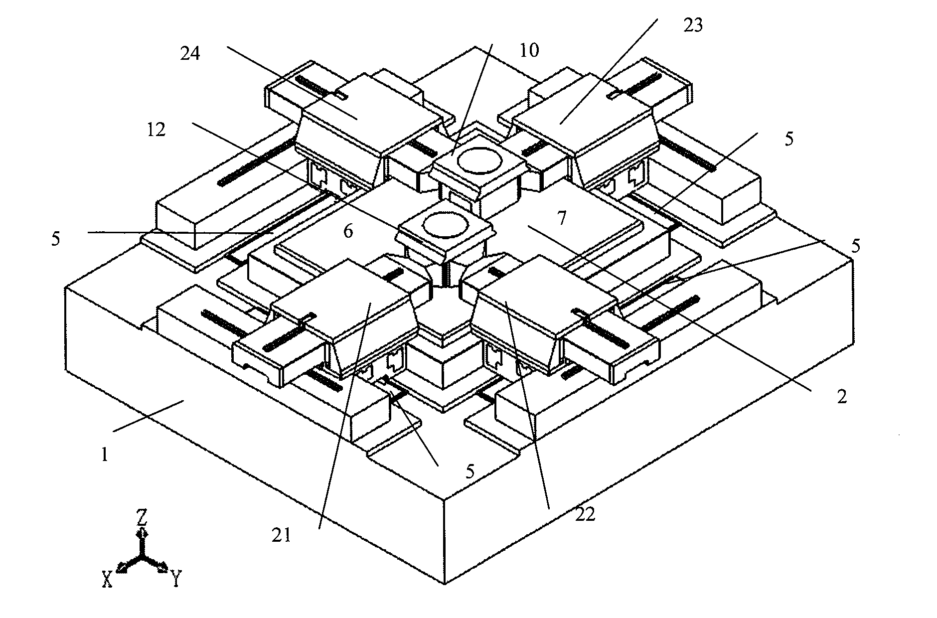
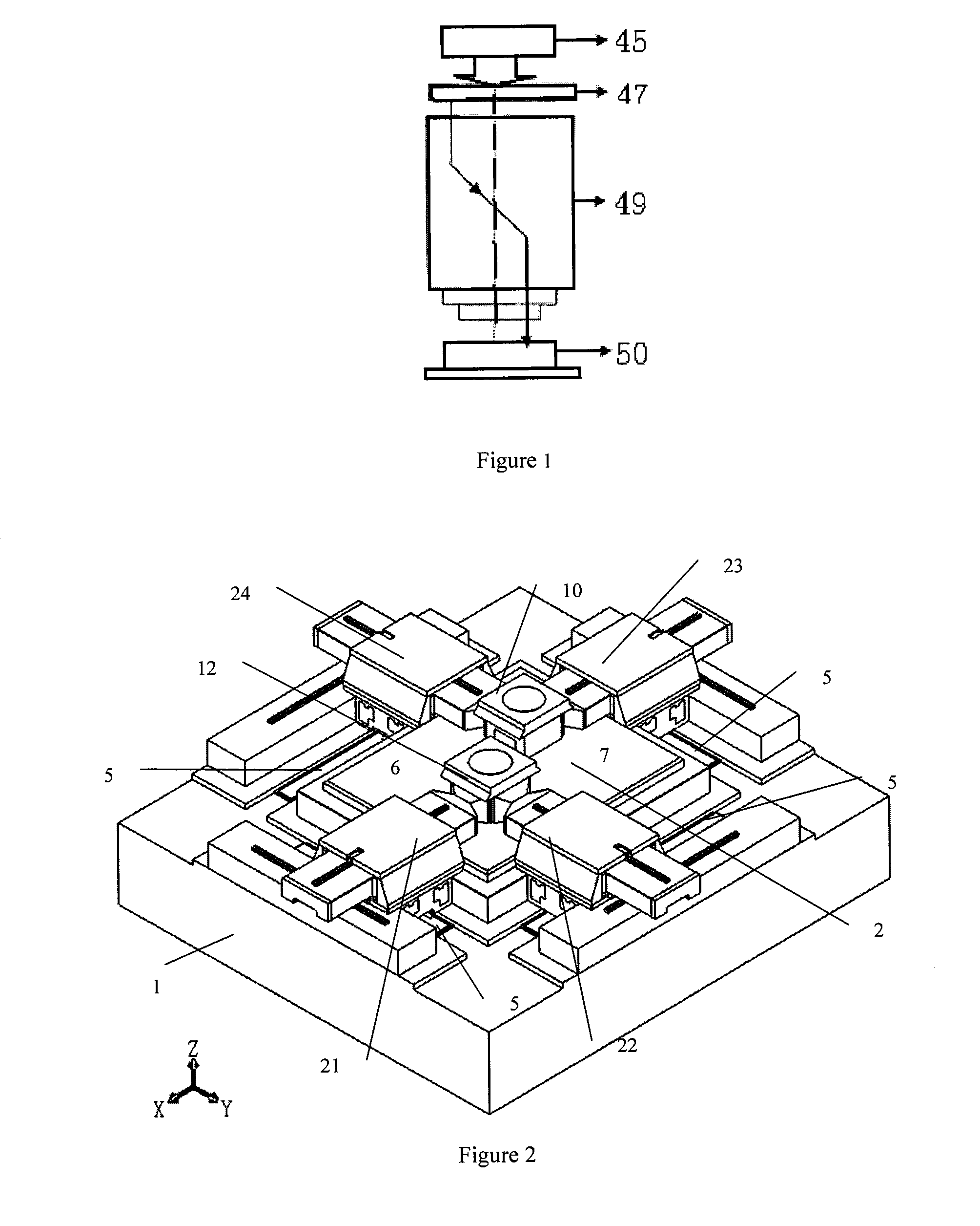
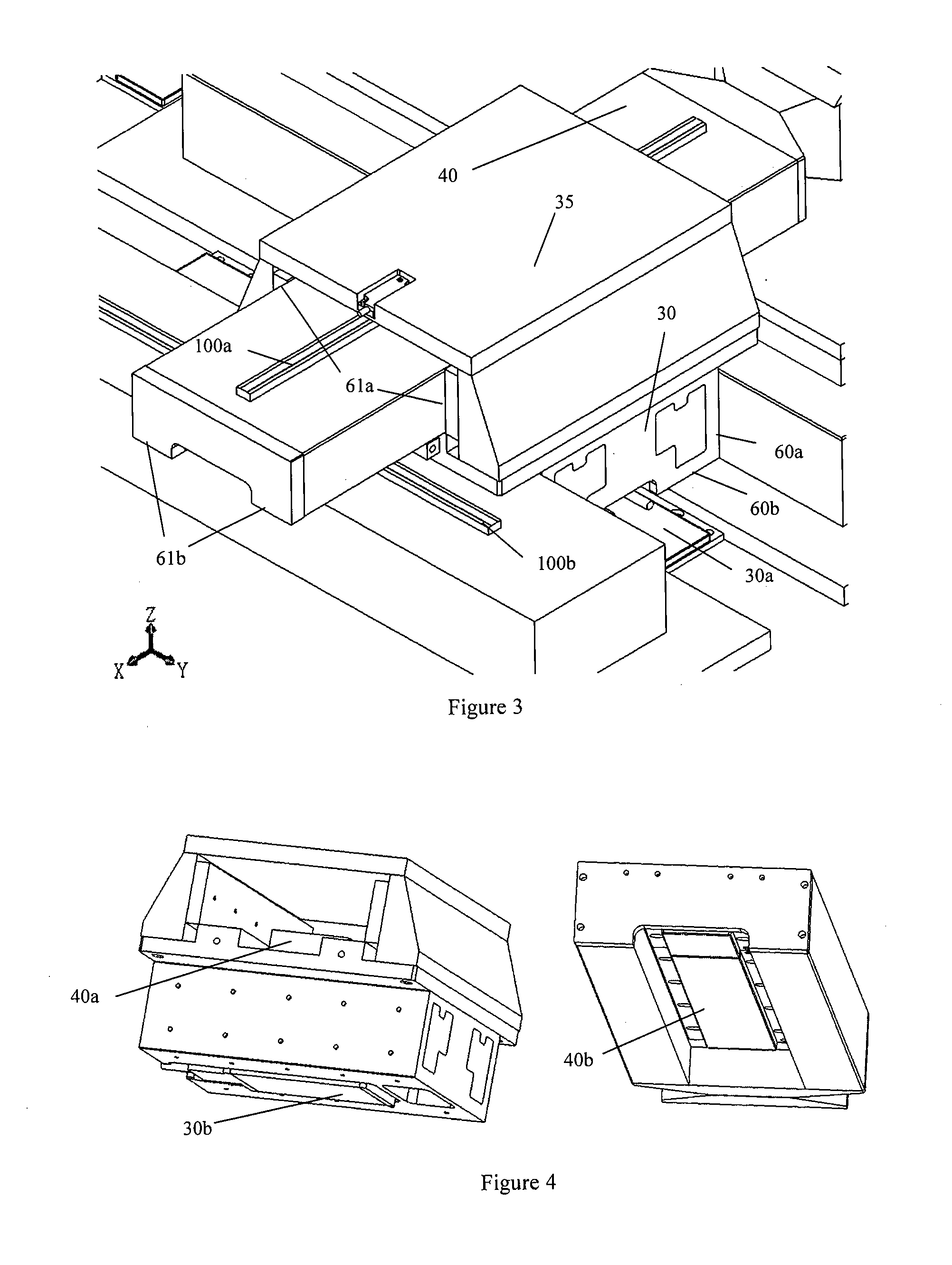
[0057]FIG. 2 shows a schematic view of a dual-stage switching system for lithographic machine according to an embodiment of the invention. The system comprises a base 1, a first wafer stage 10 to be operated in an exposure station 6, a second wafer stage 12 to be operated in a pre-processing station 7, and four 2-DOF (degree of freedom) driving units arranged on the edges of the base and movable in X direction and Y direction. The two wafer stages are arranged within a space surrounded by the four 2-DOF driving units and are suspended above the upper surface of the base by air bearings. Each of the 2-DOF driving units comprises an upper linear guide 40, a lower linear guide 30 and a guiding sleeve 35, with the upper linear guide and the lower linear guide mounted to the guiding sleeve and being perpendicular to each other. The 2-DOF driving units are coupled with the wafer stages via air bearings 80 preloaded by permanent magnets and / or by vacuum.

[0058]FIGS. 3 and 4 show the structu...


PUM


Abstract

A dual-stage switching system for lithographic machine includes a wafer stage to be operated in an exposure station and another wafer stage to be operated in a pre-processing station. The two wafer stages are provided on a base, with four 2-DOF driving units capable of moving along X direction and Y direction being provided along the edge of the base, and the wafer stages being disposed in a space surrounded by the four 2-DOF driving units and suspended on an upper surface of the base by air bearings. Each of the 2-DOF driving units includes upper and lower linear guides and a guiding sleeve, with the upper and lower linear guides being installed vertical to each other in their corresponding guiding sleeve. Two adjacent 2-DOF driving units cooperatively drive the wafer stage) to move in the X direction and Y direction.

Description

TECHNICAL FIELD[0001]The invention relates to a dual-stage switching system for a lithographic machine, especially for a semiconductor lithographic machine. The invention is applicable in semiconductor manufacture equipment field.BACKGROUND ART[0002]In the manufacturing of an integrated circuit chip, one of the most important steps comprises exposing and transferring the designed pattern for the chip onto the photoresist which covers a surface of a silicon wafer. This step is also referred to as “photolithography” in which a machine called lithographic machine (or exposure machine) is used. The characteristic line width (or resolution) and the production efficiency of the integrated circuit chip are greatly affected by the resolution and exposure efficiency of the lithographic machine. The resolution and the exposure efficiency of the lithographic machine, in turn, are mainly depended on the movement precision and the working efficiency of an ultra-precise wafer moving and positioni...

Claims


Application Information

Patent Timeline
IPC IPC(8): G03B27/58
CPCG03F7/70733G03F7/70725
Inventor ZHU, YUZHANG, MINGWANG, JINSONGLI, GUANGXU, DENGFENGYIN, WENSHENGDUAN, GUANGHONGYANG, KAIMING
Owner TSINGHUA UNIV
Why Eureka
Try Eureka