Thermal Array

Active Publication Date: 2010-08-19
SPANGLER FR LEO
View PDF8 Cites 9 Cited by
  • Summary
  • Abstract
  • Description
  • Claims
  • Application Information

AI Technical Summary

Benefits of technology

[0008]The present invention is a low energy, high efficiency thermal array consisting of a series of heater element, cooling block and heater element placed in tandem. This thermal array vastly reduces to completely eliminates the mass of the sample block while maintaining the higher efficiency of heat transfer by conduction versus convection. The array is in direct contact with the sample vessel throughout the process. This allows for greater control over thermal profile variations. Rather than converting electrical energy to heat energy and adding heat energy to the device and then transferring this energy to a sample block and finally to a sample vessel, the thermal array moves the sample vessel from one heater element to another heater element without ramping the device from one temperature to another. The thermal array converts electrical energy into

Problems solved by technology

Because going from one temperature in a sample vessel to another temperature using the thermal array requires only a fraction of

Method used


Image

  • Thermal Array
  • Thermal Array
  • Thermal Array

Examples


Example

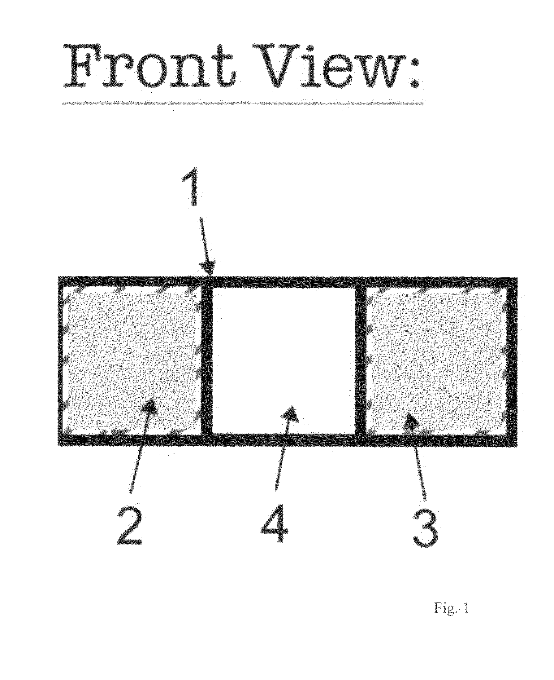
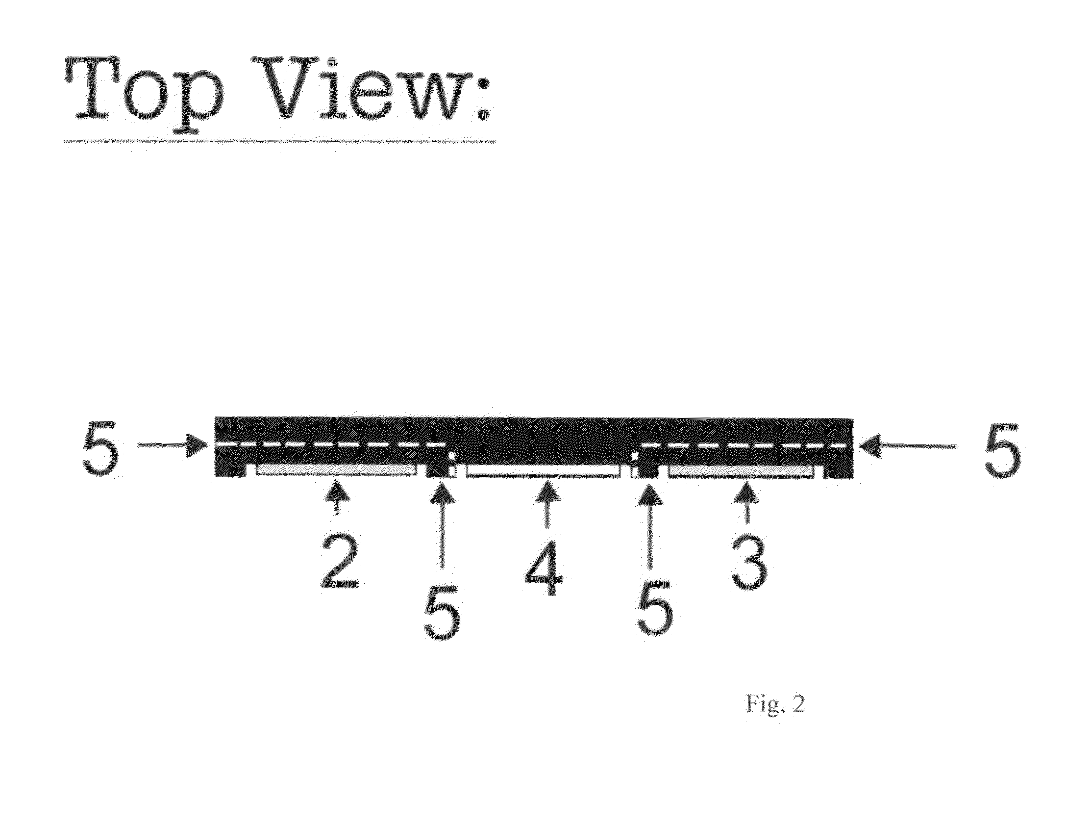
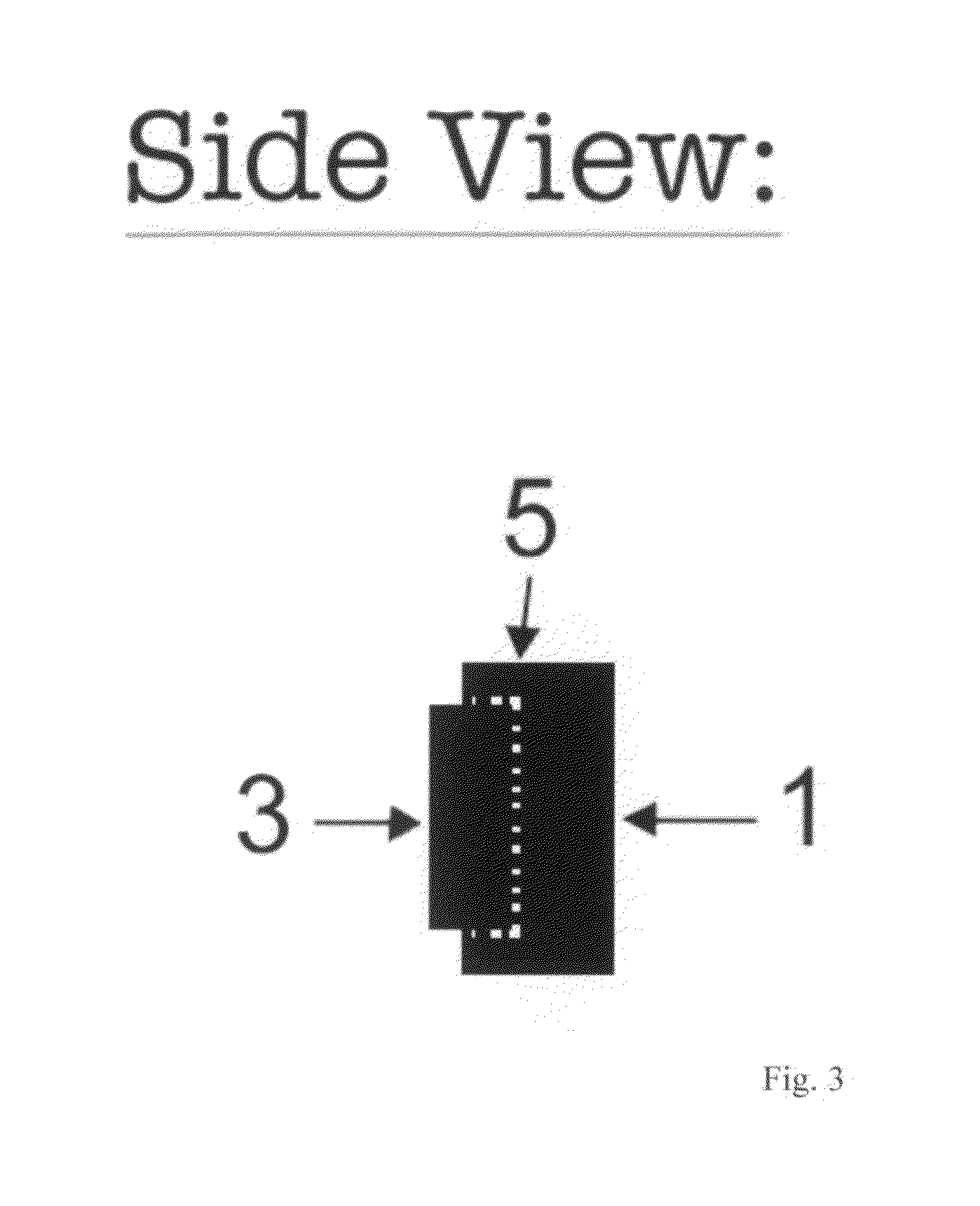
[0014]Referring now to the invention in more detail, in FIG. 1, FIG. 2 and FIG. 3 there is shown a thermal array 1 having a heating element 2 and a separate heating element 3 held in position by the entire cooling block 4. Each of the heating elements 2&3 are attached to the cooling block with insulation 5 covering all four sides and the back of the heating elements. Only the front side of the heating elements 2&3 are exposed to conduct heat to a sample vial forming a contact face.

[0015]In further detail, still referring to the invention of FIG. 1, FIG. 2 and FIG. 3, the cooling block 4 front portion and the heating elements 2&3 front portions are sufficiently wide and long for a sample reaction vessel, such as about 0.5 to 2.0 centimeters long and about 0.5 to about 2.0 centimeters wide. The actual length and width are determined by the size of the reaction vessel. The amount of insulation is large enough to thermally isolate the heating elements 2&3 from the cooling block 4.

[0016]...


PUM


Abstract

Traditional thermocyclers are heating devices that change sample temperatures by adding heat energy into a sample block that is usually a large metal block and then extracting that heat energy out of the block in a process called ramping the temperature. Presented herein is a technology that eliminates the large mass sample block and ramping temperatures in a sample block and thus in a sample vessel. This design called a Thermal Array requires a fraction of the energy used to process a sample. In addition, the array allows a much smaller thermal cycler to be designed leading to portability of a device. This technology is designed to allow optimal polymerase chain reactions to be executed.

Description

CROSS-REFERENCE TO RELATED APPLICATIONS[0001]This application claims priority to U.S. Provisional Application No. 61 / 152,546, filed on Feb. 13, 2009 by Frank Leo Spangler and entitled “Thermal Array”, which is incorporated herein by reference.STATEMENT REGARDING FEDERALLY SPONSORED RESEARCH OR DEVELOPMENT[0002]Not ApplicableREFERENCE TO SEQUENCE LISTING, A TABLE, OR A COMPUTER PROGRAM LISTING COMPACT DISK APPENDIX[0003]Not ApplicableBACKGROUND OF THE INVENTION[0004]The present invention is in the technical field of biotechnology. More particularly, the present invention is in the technical field of polymerase chain reaction (PCR) devices. More particularly, the present invention is in the technical field of portable PCR devices.[0005]Since its invention, the polymerase chain reaction (U.S. Pat. No. 4,683,202) has become a powerful force in biotechnology. It is a method to exponentially amplify essentially exact copes of a DNA segment. DNA is a double stranded molecule and when heate...

Claims


Application Information

Patent Timeline
IPC IPC(8): C12M1/38C12M1/00
CPCB01L7/5255B01L2300/0809B01L2300/1883B01L2300/1822B01L2300/1827B01L2300/1805B01L2300/0803
Inventor SPANGLER, FRANK LEO
Owner SPANGLER FR LEO
Why Eureka
Try Eureka