
Substrate transfer apparatus and substrate treatment system

a technology of substrate treatment and transfer apparatus, which is applied in the direction of conveyors, manufacturing tools, instruments, etc., can solve the problems of reducing the yield of products manufactured by the substrate treatment system, and non-negligent problems, so as to increase the flow speed of gas, reduce the substrate, and raise the substrate

Active Publication Date: 2010-08-19
TOKYO ELECTRON LTD
View PDF15 Cites 5 Cited by
  • Summary
  • Abstract
  • Description
  • Claims
  • Application Information

AI Technical Summary

Benefits of technology

[0008]The present invention has been made in consideration of the above point, and its object is to suppress adhesion of particles to a substrate in transferring the substrate, so as to improve the yield of products manufactured in a substrate treatment system.
[0011]According to the present invention, the flow rate of the gas supplied from the gas jet unit is controlled by the control unit, whereby the flow speed of the gas at the rear surface of the substrate can be controlled. Therefore, it becomes possible to raise the substrate by increasing the flow speed of the gas and to lower the substrate by decreasing the flow speed of the gas, so that the substrate can be transferred by being raised and lowered while floating in the substrate housing container. As a result, the adhesion of particles to the rear surface of the substrate which has conventionally occurred in transferring the substrate is suppressed. Thus, the yield of products manufactured in the substrate treatment system can be improved.

Problems solved by technology

The particle is a factor that reduces the yield of products manufactured by the substrate treatment system, bringing about a non-negligible problem with advancement in miniaturization of line width.

Method used


Image

  • Substrate transfer apparatus and substrate treatment system
  • Substrate transfer apparatus and substrate treatment system
  • Substrate transfer apparatus and substrate treatment system

Examples


Embodiment Construction

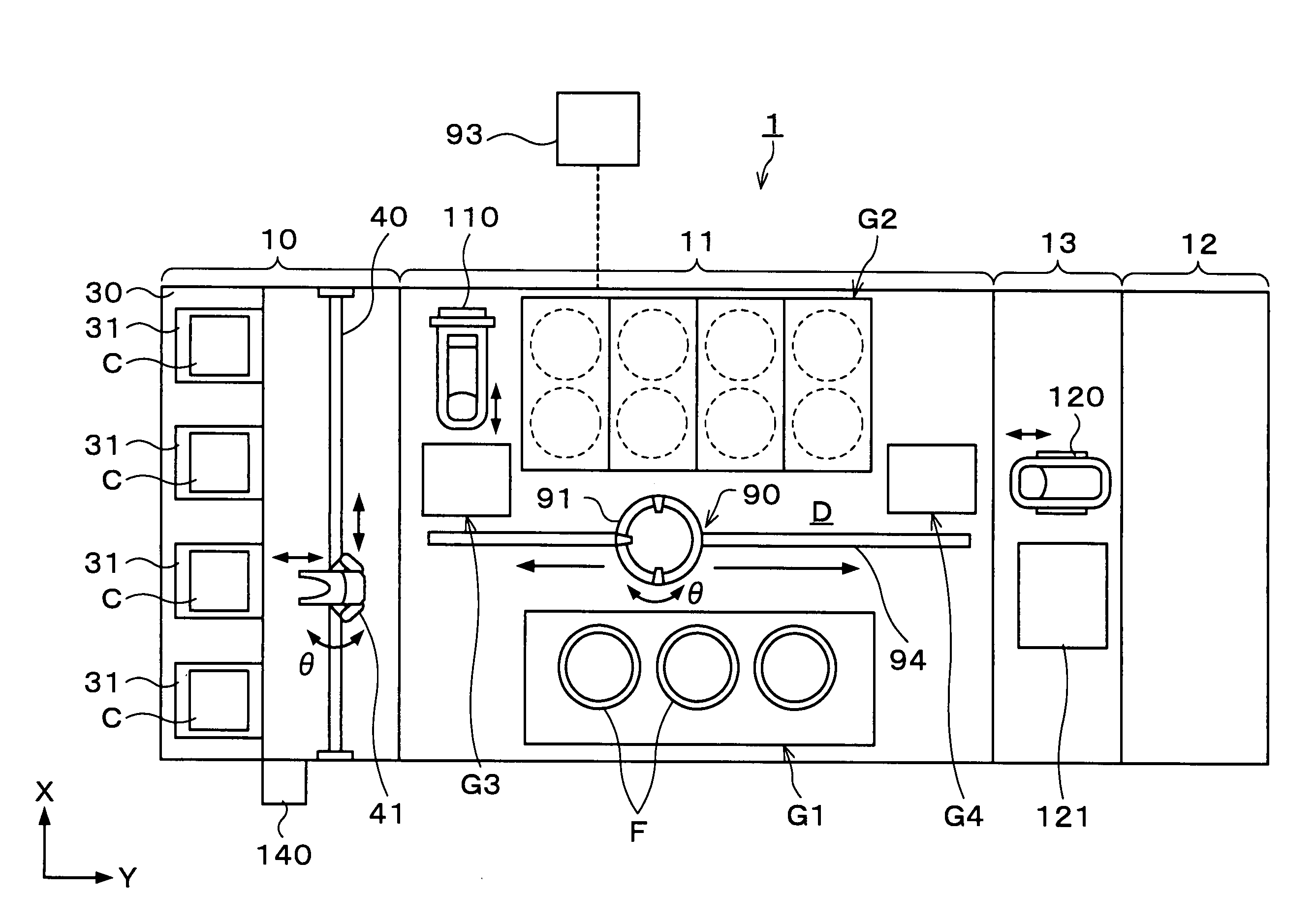
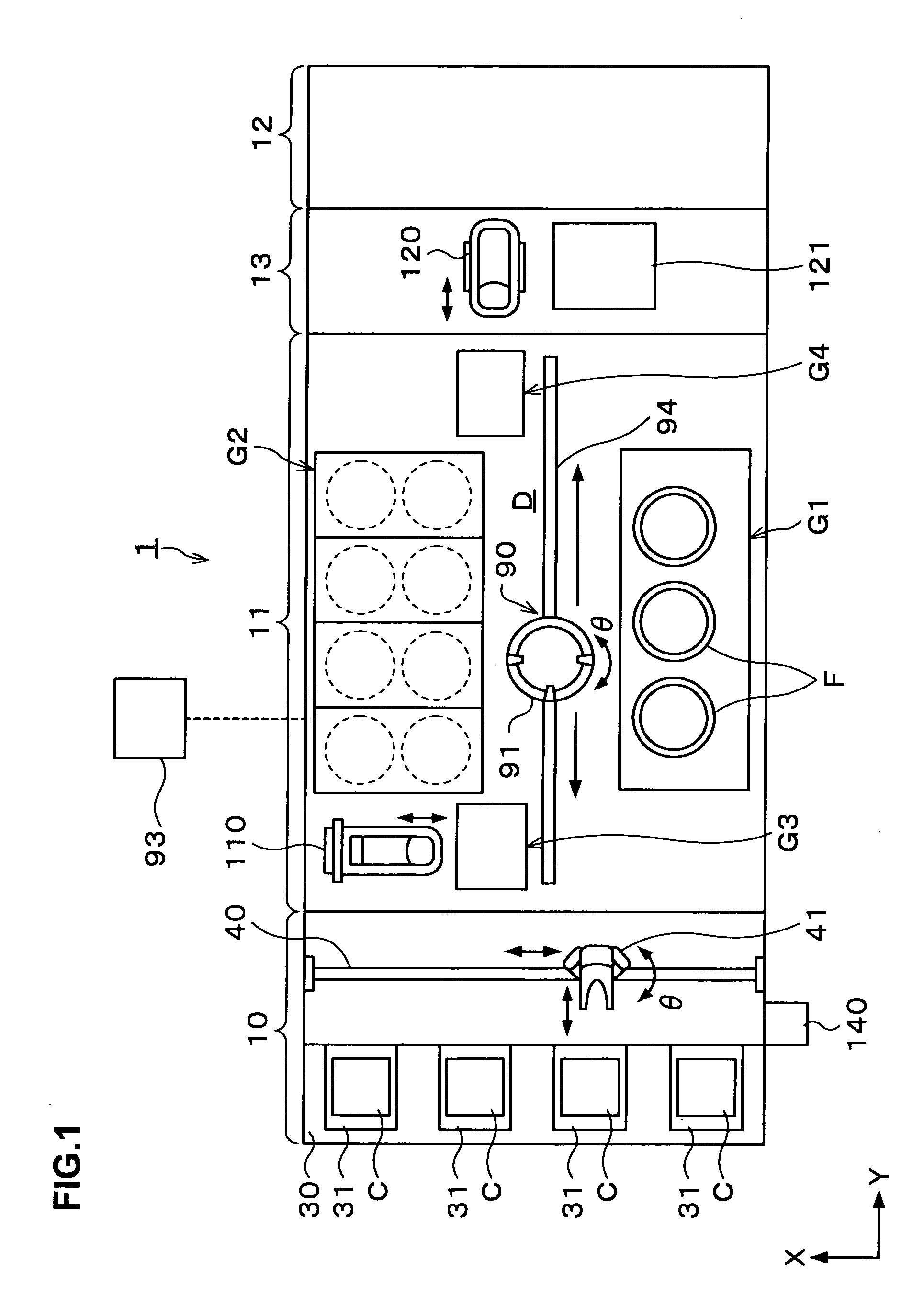
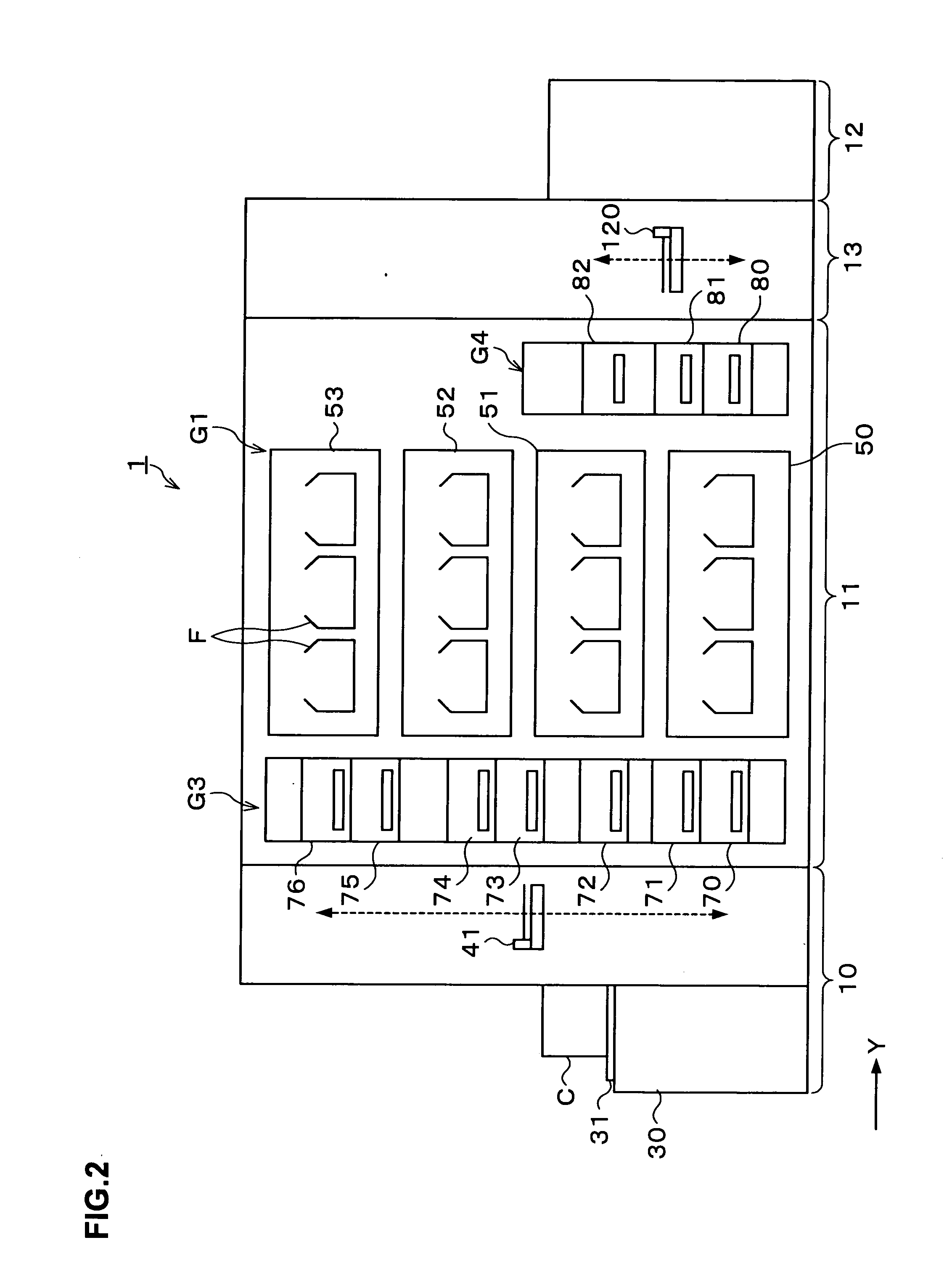
[0031]Hereinafter, embodiments of the present invention will be described. FIG. 1 is an explanatory view showing the outline of a structure of a coating and developing treatment system 1 according to the present invention.

[0032]The coating and developing treatment system 1 has, as shown in FIG. 1, a structure in which, for example, a cassette station 10 into / from which cassettes C are transferred from / to the outside; a treatment station 11 including a plurality of various kinds of treatment apparatuses each for performing predetermined treatment in a manner of single-substrate treatment in photolithography processing; and an interface station 13 for delivering the substrate W to / from an aligner 12 adjacent to the treatment station 11, are integrally connected. Note that in this embodiment, for example, a semiconductor wafer is used as the substrate W.

[0033]In the cassette station 10, a cassette mounting table 30 is provided. On the cassette mounting table 30, a plurality of, for exa...


PUM

PropertyMeasurementUnit
Shapeaaaaaaaaaa
Heightaaaaaaaaaa
Circumferenceaaaaaaaaaa

Abstract

The present invention is a transfer apparatus for a substrate, including a substrate housing container housing a substrate therein and having a transfer-in / out port for the substrate formed in a side surface thereof; a gas jet unit jetting a predetermined gas toward a rear surface of the substrate in the substrate housing container; and a control unit regulating a supply amount of the predetermined gas supplied from the gas jet unit to control the substrate in the substrate housing container to a predetermined height.

Description

BACKGROUND OF THE INVENTION[0001]1. Field of the Invention[0002]The present invention relates to a transfer apparatus for a substrate such as a semiconductor wafer or the like, and a substrate treatment system having the substrate transfer apparatus.[0003]2. Description of the Related Art[0004]In a photolithography processing in a manufacturing process of a semiconductor device, for example, resist coating treatment of applying a resist solution onto a substrate such as a semiconductor wafer or the like to form a resist film, exposure processing of exposing the resist film to a predetermined pattern, developing treatment of developing the exposed resist film and so on are performed.[0005]A series of the treatments and processing is usually performed using a coating and developing treatment system. The coating and developing treatment system has a cassette station for transferring in / out substrates, for example, in a unit of cassette, a treatment station in which a plurality of treat...

Claims


Application Information

Patent Timeline
IPC IPC(8): H01L21/677G06F7/00H01L21/673
CPCH01L21/67017H01L21/6715H01L21/6719Y10T408/5612Y10T408/559Y10T408/29H01L21/67196B65G49/065H01L21/67784
Inventor YANO, MISUTERUDOUKI, YUICHITOMITA, HIROSHI
Owner TOKYO ELECTRON LTD
Learn More