

Acceleration sensor and electronic device
a sensor and acceleration technology, applied in the direction of speed/acceleration/shock measurement, flexible microstructure devices, instruments, etc., can solve the problems of reducing shock resistance and collision damage between the movable unit and the support member, and achieve the effect of increasing the shock resistance of electronic devices
- Summary
- Abstract
- Description
- Claims
- Application Information
AI Technical Summary
Benefits of technology
Problems solved by technology
Method used
Image

Examples
first embodiment
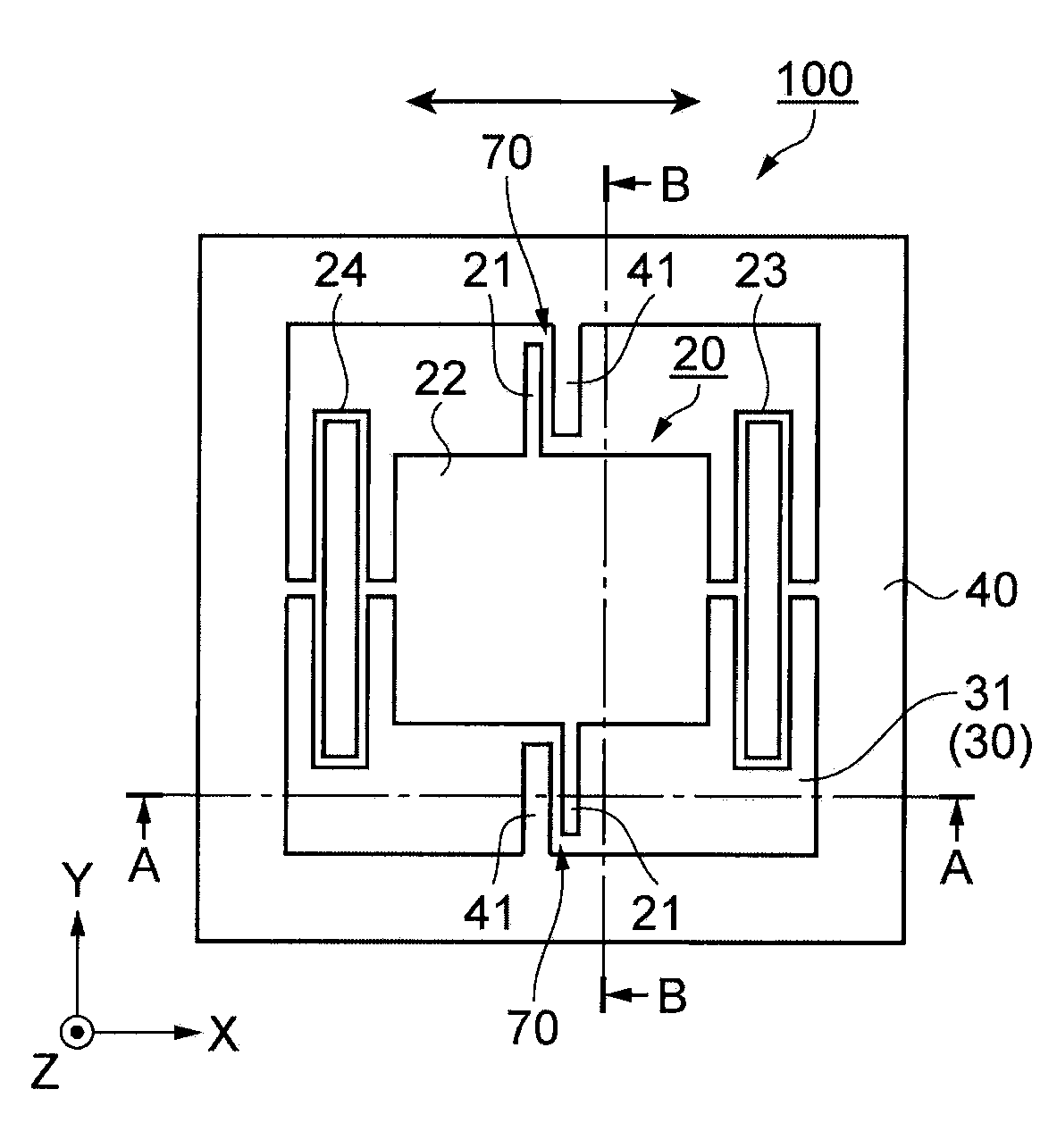
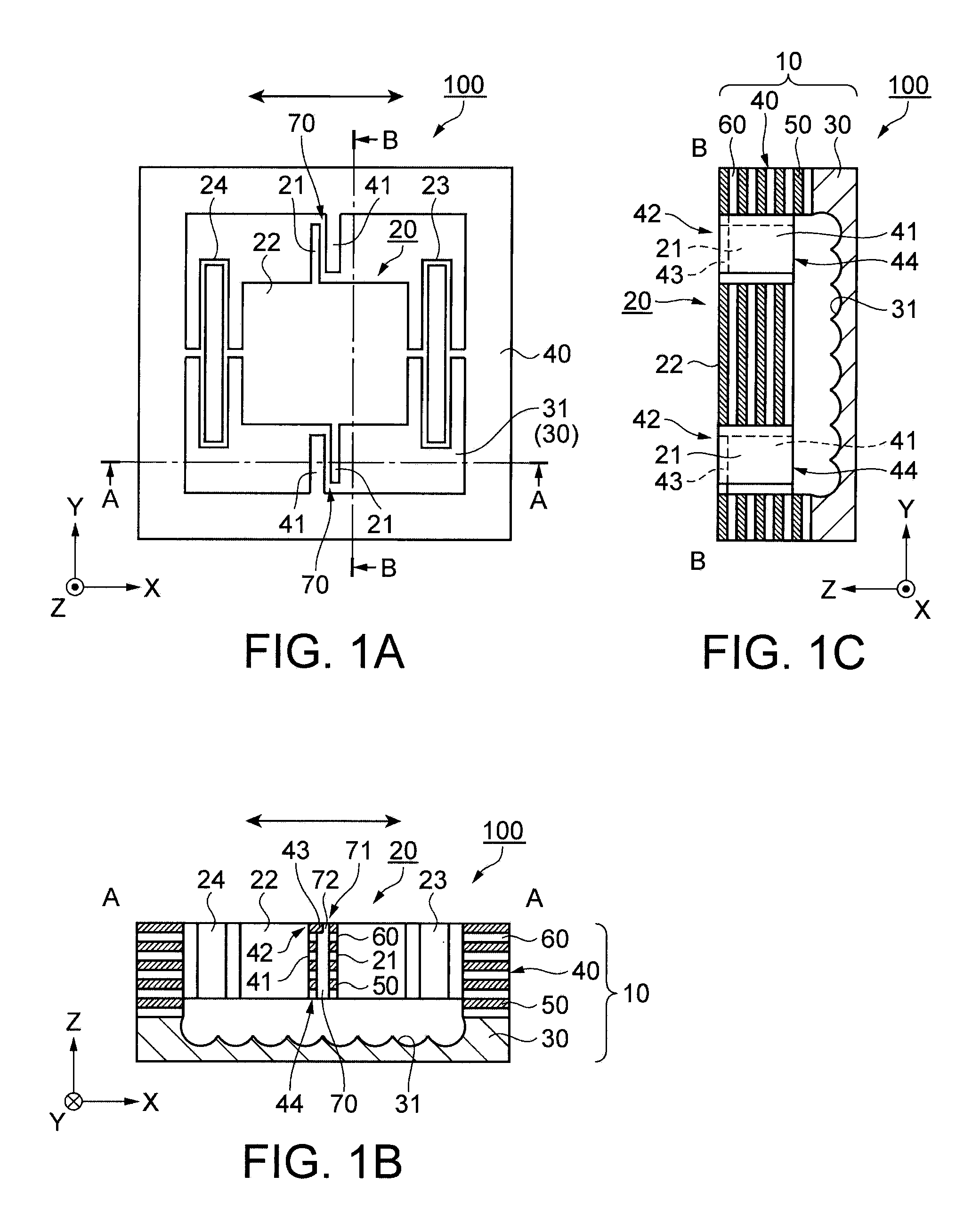
[0038]FIGS. 1A through 1C schematically illustrate an acceleration sensor 100 according to a first embodiment. FIG. 1A is a plan view schematically showing the acceleration sensor 100. FIG. 1B is a cross-sectional view schematically showing the acceleration sensor 100 taken along a line A-A in FIG. 1A. FIG. 1C is a cross-sectional view schematically showing the acceleration sensor 100 taken along a line B-B in FIG. 1A. In these figures, X, Y, and Z axis directions are shown.
[0039]Double arrows in the figures represent the acceleration detection direction. In this embodiment, the X axis direction corresponds to the acceleration detection direction.
[0040]As illustrated in FIGS. 1A through 1C, the acceleration sensor 100 includes a support member 10 and a movable unit 20.
[0041]The support member 10 has a substrate 30 and a support unit 40 provided on the substrate 30. The movable unit 20 is also disposed on the substrate 30.
[0042]The substrate 30 is a silicon substrate which has a conc...
second embodiment
[0074]FIGS. 3A through 3C schematically illustrate an acceleration sensor 200 according to a second embodiment. FIG. 3A is a plan view schematically showing the acceleration sensor 200. FIG. 3B is a cross-sectional view schematically showing the acceleration sensor 200 taken along a line A-A in FIG. 3A. FIG. 3C is a cross-sectional view schematically showing the acceleration sensor 200 taken along a line B-B in FIG. 3A. In these figures, X, Y, and Z axis directions are shown. Double arrows in the figures indicate the acceleration detection direction. In this embodiment, the acceleration detection direction corresponds to the X axis direction similarly to the first embodiment.
[0075]Similar reference numbers are given to components similar to those in the first embodiment. In the following explanation, the points different from the first embodiment are chiefly touched upon.
[0076]As illustrated in FIGS. 3A through 3C, the structure of the acceleration sensor 200 is substantially simila...
third embodiment
[0090]FIGS. 5A through 5C schematically illustrate an acceleration sensor 300 according to a third embodiment. FIG. 5A is a plan view schematically showing the acceleration sensor 300. FIG. 5B is a cross-sectional view schematically showing the acceleration sensor 300 taken along a line A-A in FIG. 5A. FIG. 5C is a cross-sectional view schematically showing the acceleration sensor 300 taken along a line B-B in FIG. 5A. In these figures, X, Y, and Z axis directions are shown. Double arrows in the figures indicate the acceleration detection direction. In this embodiment, the acceleration detection direction corresponds to the X axis direction.
[0091]Similar reference numbers are given to components similar to those in the first and second embodiments. In the following explanation, the points different from the first and second embodiments are chiefly touched upon.
[0092]According to this embodiment, the movable electrode 21 has a concave cross-sectional shape, and the fixed electrode 41...
PUM
 Abstract
Description
Claims
Application Information