Oxyfuel Combustion Boiler Plant and Operating Method for the Same

a technology of oxyfuel combustion and boiler plant, which is applied in the direction of combustion control, combustion types, separation processes, etc., can solve the problems of low carbon dioxide concentration in exhaust gas, difficult to remove carbon dioxide, and low efficiency of combustion boilers

Active Publication Date: 2010-08-26
MITSUBISHI POWER LTD
View PDF72 Cites 11 Cited by
  • Summary
  • Abstract
  • Description
  • Claims
  • Application Information

AI Technical Summary

Benefits of technology

[0016]According to the present invention, the discharge quantity of carb...

Problems solved by technology

When starting the boiler using the air combustion system, the carbon dioxide concentration in the exhaust gas is low, so it is difficult to remove carbon dioxide by the CO2 capture facility used in the oxyfuel combustion.
However, the main objec...

Method used


Image

  • Oxyfuel Combustion Boiler Plant and Operating Method for the Same
  • Oxyfuel Combustion Boiler Plant and Operating Method for the Same
  • Oxyfuel Combustion Boiler Plant and Operating Method for the Same

Examples


embodiment 1

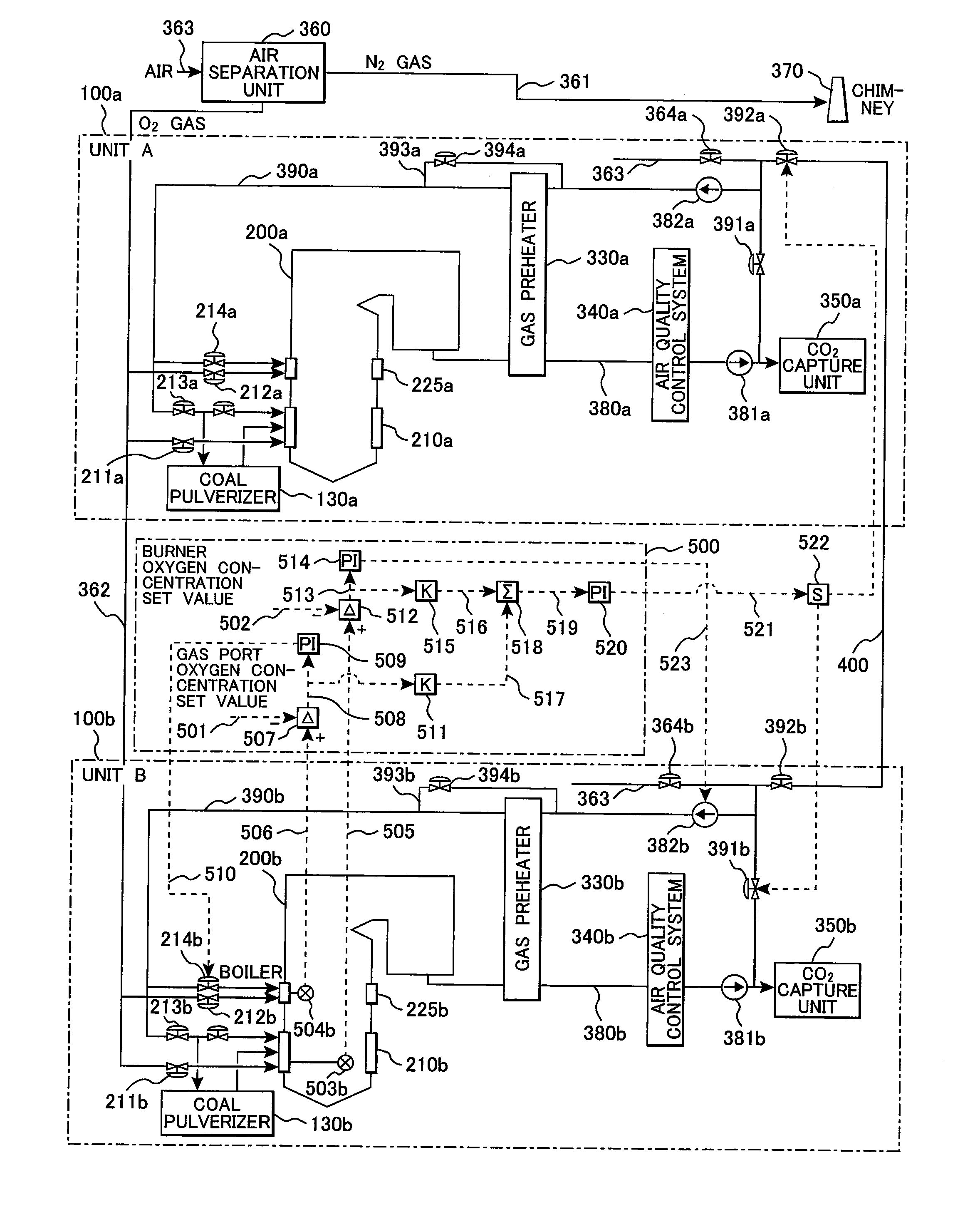
[0025]FIG. 1 shows the constitution of the boiler plant using coal as fuel.

[0026]In FIG. 1, this embodiment of the boiler plant in the present invention shows the case that there are two plants with the same structure (hereinafter referred to as units). With respect to the numbers shown in the drawing, a is used for the unit A and b is used for the unit B.

[0027]This embodiment shows a thermal power plant for generating steam using a boiler 200. The system of a combustion exhaust gas 380 discharged from the boiler 200 includes a gas preheater 330, an air quality control system (AQCS) 340 for purifying exhaust gas, a fan 381 for permitting gas to flow, a CO2 capture unit 350 for cooling, liquefying, and capturing carbon dioxide in the exhaust gas, and a chimney 370 for discharging gas mainly including nitrogen and oxygen remaining after the capture of carbon dioxide (the pipe from the CO2 capture unit 350 to the chimney 370 is not drawn).

[0028]This embodiment aims at a boiler of the o...

embodiment 2

[0069]This embodiment as shown in FIG. 4, when starting the first unit A among two units (unit A and unit B), indicates a method for reducing the carbon dioxide quantity discharged from the first unit A. FIG. 4 shows the constitution of the unit A.

[0070]The differences from the unit constitution of the embodiment shown in FIG. 1 are the oxygen gas supply method and the supply method of exhaust gas mainly including carbon dioxide. In the present embodiment, the flow path through which oxygen gas flows from the air separation unit 360 to the burner 210a and the gas port 225a is branched halfway and includes an oxygen storage line 611. On the oxygen storage line 611, an oxygen storage tank 612 is installed and the oxygen storage tank 612 stores oxygen gas. Therefore, the oxygen storage tank 612 can also supply oxygen gas.

[0071]The oxygen quantity stored in the oxygen storage tank 612 is controlled by an oxygen storage quantity regulating valve 610 on the upstream side and the oxygen qu...


PUM


Abstract

An oxyfuel combustion boiler plant having a first boiler and a second boiler for injecting gas including oxygen in higher concentration than that in the air, gas including carbon dioxide in higher concentration than that in the air, and fuel from a burner and generating steam by combustion gas in a furnace, respectively, comprising:
    • an exhaust gas supply pipe for supplying exhaust gas discharged from the first boiler to a burner of the second boiler, and a gas flow rate control apparatus for controlling a flow rate of exhaust gas flowing through the exhaust gas supply pipe.

Description

CLAIM OF PRIORITY[0001]The present application claims priority from Japanese patent application serial No. 2009-041637, filed on Feb. 25, 2009, the content of which is hereby incorporated by reference into this application.BACKGROUND OF THE INVENTION[0002]1. Field of the Invention[0003]The present invention relates to an oxyfuel combustion boiler plant and an operating method for the oxyfuel combustion boiler plant.[0004]2. Description of Related Art[0005]A thermal power plant including a boiler and a steam turbine as main components is pointed out that the discharge quantity of carbon dioxide that is a global warming factor is larger than those of other power generation systems.[0006]Therefore, when burning fuel by a boiler, a method for burning fuel using high-purity oxygen instead of air is proposed. Hereinafter, a burning method using oxygen is called oxyfuel combustion and a burning method using air is called air combustion.[0007]The oxyfuel combustion changes the greater part ...

Claims


Application Information

Patent Timeline
IPC IPC(8): F23N1/02F23J15/00F23B80/02C01B32/50
CPCF01K13/02F23C9/003F23C9/08F23C2202/00F23C2202/50F23L7/007Y02C10/06F23N2037/04F23N2041/10Y02E20/328Y02E20/344F23L2900/07001Y02E20/322F23N2027/02F23N2227/02F23N2237/04F23N2241/10Y02C20/40Y02E20/32Y02E20/34
Inventor YAMADA, AKIHIROSHIBATA, TSUYOSHIHAYASHI, YOSHIHARU
Owner MITSUBISHI POWER LTD
Why Eureka
Try Eureka