Superconducting switch operation

a superconducting switch and superconducting magnet technology, applied in superconducting magnets/coils, magnetic bodies, relays, etc., can solve problems such as quenching of the magnetic field, and achieve the effect of low resistance associated with the auxiliary superconducting switch, low voltage drop across and low power dissipation in the main superconducting switch

Inactive Publication Date: 2010-08-26
AGILENT TECH INC
View PDF4 Cites 7 Cited by
  • Summary
  • Abstract
  • Description
  • Claims
  • Application Information

AI Technical Summary

Benefits of technology

[0013]The resistance value of the auxiliary superconducting switch needs to be low enough so that the voltage drop across the main superconducting switch is low and therefore the power dissipation in the main superconducting switch is also low. The resistance associated with the auxiliary superconducting switch should be very low, for example of the order of 10−8Ω. This allows the main superconducting switch to cool down and close, and the current to then transfer from the auxiliary superconducting switch to the main superconducting switch with a time constant equivalent to L / R seconds, where L is the overall inductance of the auxiliary superconducting switch and the main superconducting switch and R is the resistance of the auxiliary superconducting switch only. When the main superconducting switch opens and the current is diverted to the auxiliary superconducting switch, before eventually returning to the main superconducting switch, the loss of energy during the process is minimal (typically approximately 1 Joule).

Problems solved by technology

However it has been observed that, in the absence of such pretraining, there have been occasions where, when an event has taken place causing the main superconducting switch to suddenly open, the magnet current has failed to transfer to the auxiliary superconducting switch and as a result the magnet has quenched.
This can be a very costly result as the magnet would then have to be returned to the manufacture and conditioned all over again.

Method used


Image

  • Superconducting switch operation
  • Superconducting switch operation
  • Superconducting switch operation

Examples


second embodiment

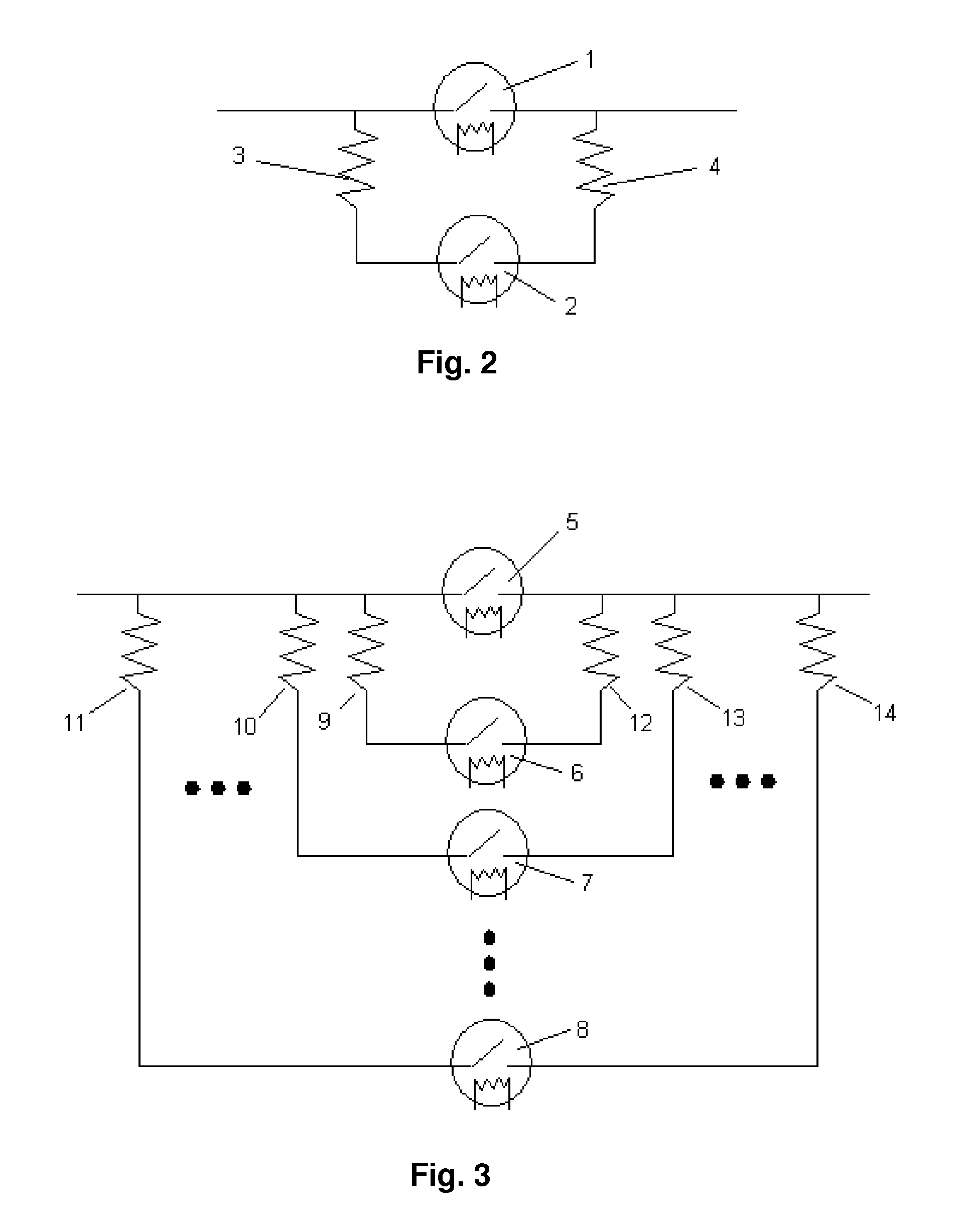
[0025]If the magnet operating current is high, it is not possible for a single auxiliary superconducting switch to handle the operating current when the main superconducting switch is opened, due to the high current rate of change from the main superconducting switch to the auxiliary superconducting switch. In this event then more than one auxiliary superconducting switch is required. FIG. 3 shows superconducting switch system in which two or more auxiliary superconducting switches 6, 7, 8 are connected to the magnet circuit in parallel with the main superconducting switch 5, which carries the magnet operating current during normal operation of the magnet circuit, by resistive solder joints 9, 10, 11, 12, 13, 14. If the main superconducting switch 5 quenches (or opens), the current will transfer to the auxiliary superconducting switches 6, 7, 8 through the solder joints 9, 10, 11, 12, 13, 14. Subsequently, after the main superconducting switch 5 has recovered, the voltage across the...

third embodiment

[0026]To reduce the current transfer rate from the main superconducting switch to the auxiliary superconducting switch, an inductor may be added to the magnet circuit. FIG. 4 shows a third embodiment in which an inductor 16 is serially connected between the main superconducting switch 15 and the auxiliary superconducting switch 17. The inductor 16 serves to reduce the current transfer rate from the main superconducting switch 15 to the auxiliary superconducting switch 17, which is resistively connected to the circuit through the connecting parts 18 and 19 generally constituted by solder joints. If the main superconducting switch 15 quenches, the current will transfer to the auxiliary superconducting switch 17 through the connecting parts 18 and 19. Subsequently, after the main superconducting switch 15 and the inductor 16 have recovered, the voltage across the connecting parts 18 and 19 will drive the current back to the main superconducting switch 15. The presence of the inductor 1...

seventh embodiment

[0030]In a seventh embodiment as shown in FIG. 8, a multi-strand superconducting switch 33 is provided in place of both the main superconducting switch and the auxiliary superconducting switch. One portion of the strands of the switch 33 is connected by a superconducting joint to the magnet circuit to serve as the main superconducting switch, and the other portion of the strands of the switch 33 is resistively connected to the magnet circuit through connecting parts 34 and 35 to serve as the auxiliary superconducting switch so that, if the main superconducting switch quenches, the current will transfer to the auxiliary superconducting switch through the connecting parts 34 and 35. Subsequently, after the portion of the strands constituting the main superconducting switch has recovered, the voltage across the connecting parts 34 and 35 will drive the operating current back to the portion of the strands constituting the main superconducting switch. A preconditioning procedure is carri...


PUM


Abstract

A method of operating a superconducting switch system to protect against quenching in a superconducting magnet circuit is provided. The system comprises a magnet circuit, a main superconducting switch and an auxiliary superconducting switch connected in parallel thereto by low resistance connecting parts. In an initial magnet energisation procedure, after establishing superconducting flow in the circuit, the main and auxiliary switches are closed to cause current to persist in the circuit without further power input. If the main switch quenches, the current will transfer to the auxiliary switch through the resistive connecting parts. Upon restoring the main switch to the superconducting state, the voltage drop through the resistive connecting parts will drive the current back through the main switch. A preconditioning procedure is carried out as part of the magnet energisation procedure to ensure that opening the main switch will establish superconducting current through the auxiliary switch.

Description

CROSS REFERENCE TO RELATED APPLICATIONS[0001]The subject patent application is claiming a priority of Great Britain Patent Application No. 0719843.5 filed in the Great Britain Patent Office on 11 Oct. 2007.FIELD OF THE INVENTION[0002]This invention relates to methods of operating superconducting switch systems and persistent mode superconducting magnet systems, and is concerned more particularly with the recovery of the quenching of a superconducting switch during superconducting magnet operation.BACKGROUND OF THE INVENTION[0003]Persistent mode superconducting magnets, used in nuclear magnetic resonance spectroscopy (NMR), magnet resonance imaging (MRI), electronic paramagnetic resonance (EPR) and Fourier transform mass spectroscopy (FTMS), incorporate a persistent switch, also referred to as a “main superconducting switch”, which when closed permits the superconducting current flow within the magnet circuit to persist without any further injection of current into the circuit being ...

Claims


Application Information

Patent Timeline
Patent Type & Authority Applications(United States)
IPC IPC(8): H01H47/00
CPCH01F6/02Y02E40/68H02H7/001H01L39/16Y02E40/60H10N60/30H01F6/008
Inventor ZHANG, SHAOHAIMARSHALL, ALEXANDER JOHNIOANNIDES, A.C.
Owner AGILENT TECH INC
Why Eureka
Try Eureka