Superconducting connection between MgB2 superconducting wires via a compressed element made from HTS powder

a superconducting wire and superconducting element technology, applied in the direction of superconducting magnets/coils, connection contact materials, magnetic bodies, etc., can solve the problems of relatively small current carrying capacity of joints, relatively high cost of nbti, and superconducting connection points, etc., to improve pressing behavior and/or solidity of compressed elements, the effect of high current carrying capacity

Inactive Publication Date: 2010-08-26
BRUKER EAS
View PDF7 Cites 8 Cited by
  • Summary
  • Abstract
  • Description
  • Claims
  • Application Information

AI Technical Summary

Benefits of technology

[0020]The invention provides in total a simple and inexpensive method for producing high-quality joints for connecting MgB2 superconducting wires, which can be technically realized without problems as a standard industrial procedure.
[0029]In one preferred embodiment, the superconducting matrix is surrounded by a coating. The coating may have already been provided during compression (container) or also be arranged around the compressed element after compression (protective coating). The coating may, in particular, be formed from metal (e.g. as a metal container) or also comprise a plastic resin into which the superconducting matrix is cast. The coating thereby tightly holds the compressed HTS powder together, thereby safeguarding the superconducting connection and, in particular, preventing rupture of the superconducting connection.

Problems solved by technology

Since this low transition temperature requires cooling with cryogenic helium (boiling point approximately 4K), the use of NbTi is relatively expensive.
One difficulty with the technical use of the MgB2 superconducting system is the provision of superconducting connecting points (“joints”), in particular, between two MgB2 superconducting wires.
The generated MgB2 is, however, highly porous and the resulting current carrying capacity of the joint is relatively small.

Method used


Image

  • Superconducting connection between MgB2 superconducting wires via a compressed element made from HTS powder
  • Superconducting connection between MgB2 superconducting wires via a compressed element made from HTS powder
  • Superconducting connection between MgB2 superconducting wires via a compressed element made from HTS powder

Examples


Embodiment Construction

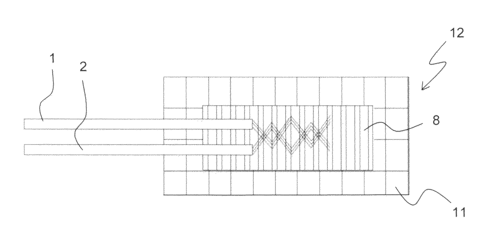
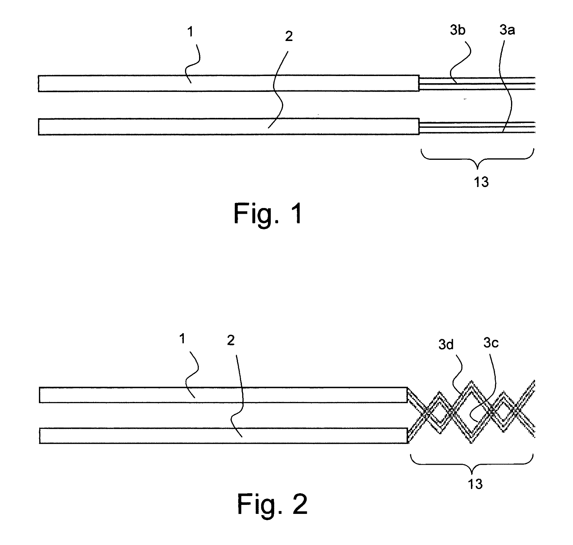
[0039]FIG. 1 shows two superconducting wires 1, 2, each comprising several filaments 3a, 3b that contain MgB2.

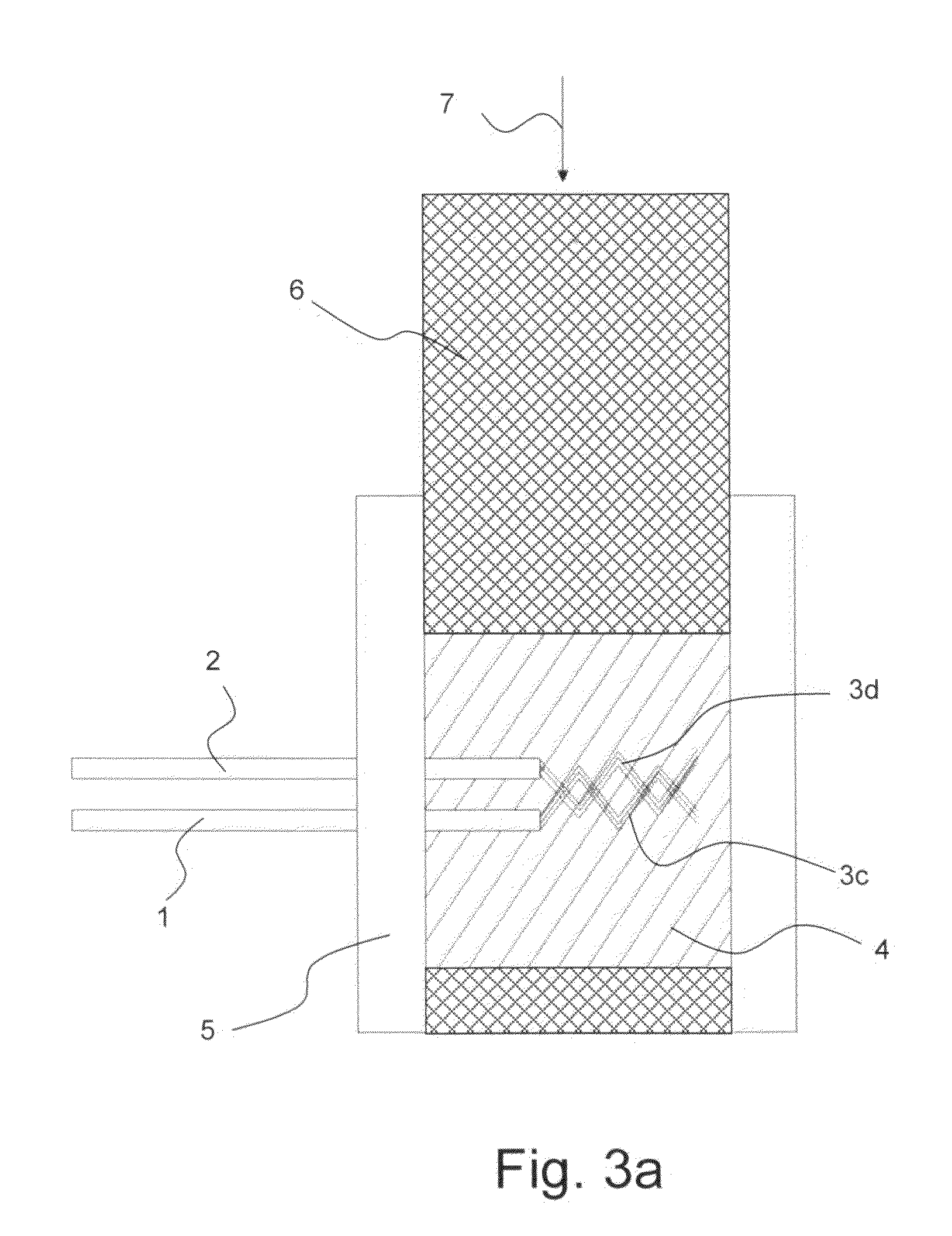
[0040]Each filament 3a, 3b is exposed in one end region 13 (in FIG. 1 on the right-hand side). Towards this end, a coating of Monel, Fe, Nb, Ta, Ti, stainless steel, Ni, Cu or Cu alloy has been removed in the end region 13 of the illustrated wires 1, 2, e.g. through etching (exposure may also be realized by other chemical and / or mechanical methods, e.g. grinding or abrasion; it is thereby not absolutely necessary to remove all coatings). The filaments 3a,3b of the two wires 1, 2 shall be superconductingly connected in accordance with the invention (cf. FIGS. 3a to 6). Towards this end, the filaments 3a, 3b of the various wires 1, 2, should be brought into the direct vicinity of each other.

[0041]FIG. 2 shows, similarly to FIG. 1, two superconducting wires 1, 2, each also comprising several filaments 3c, 3d, which are exposed in an end region 13 and contain MgB2, and being int...


PUM

PropertyMeasurementUnit
transition temperatureaaaaaaaaaa
boiling pointaaaaaaaaaa
transition temperatureaaaaaaaaaa

Abstract

A method for connecting two or more superconducting wires (1, 2), each comprising at least one filament (3a-3b) that contains MgB2, wherein the superconducting connection is realized through exposed end regions (13) of the filaments (3a-3d) via a superconducting matrix, is characterized in that a bulk powder (4) of a high-temperature superconductor (HTS) powder with a transition temperature of Tc>40K is provided, into which the exposed end regions (13) of the filaments (3a-3d) project, wherein the Boron of the Boron powder of the bulk powder (4) is in amorphous modification, and the bulk powder (4) is compacted together with the projecting exposed end regions (13) of the filaments (3a-3d) to form a compressed element (8). The method improves the quality, in particular, the current carrying capacity and the critical magnetic field strength of a superconducting connection of two MgB2 wires.

Description

[0001]This application claims Paris Convention of DE 10 2009 010 011.3 filed Feb. 21, 2009 the complete disclosure of which is hereby incorporated by reference.BACKGROUND OF THE INVENTION[0002]The invention concerns a method for connecting two or more superconducting wires, each comprising at least one filament that contains MgB2, wherein the superconducting connection is realized by exposed end regions of the filaments via a superconducting matrix.[0003]A method of this type is disclosed in U.S. Pat. No. 7,226,894 B2.[0004]Superconducting wires, through which an electric current can flow without loss, are used in a plurality of ways, in particular, for high-field magnet coils. Superconducting materials thereby become superconducting only below a material-specific transition temperature Tc such that superconducting materials must be cooled for technical use. One of the most important superconducting materials in the technical field is NbTi which has a transition temperature of appro...

Claims


Application Information

Patent Timeline
Patent Type & Authority Applications(United States)
IPC IPC(8): H01B12/04H01L39/24
CPCH01L39/02Y10T29/49014H01R4/68C04B37/005C04B37/025C04B2235/524C04B2235/604C04B2235/608C04B2237/06C04B2237/09C04B2237/121C04B2237/124C04B2237/125C04B2237/36H01R4/08H10N60/80
Inventor TENBRINK, FELICITASAUBELE, ANDREGLUECKLICH, VOLKERSAILER, BERNDSCHLENGA, KLAUS
Owner BRUKER EAS
Why Eureka
Try Eureka