Diamond LED devices and associated methods

Active Publication Date: 2010-09-02
SUNG CHIEN MIN
15 Cites 16 Cited by

AI-Extracted Technical Summary

Problems solved by technology

As electronic circuitry increases in speed and decreases in size, cooling of such devices becomes problematic.
As it builds, heat can cause various thermal problems associated with such electronic components.
Significant amounts of heat can affect the reliability of an electronic device, or even cause it to fail by, for example, causing burn out or shorting both within the electronic components themselves and across the surface of the printed circuit board.
Thus, the buildup of heat can ultimately affect the functional life o...

Benefits of technology

[0007]Accordingly, the present invention provides semiconductor devices having improved thermal properties and methods for making such devices. In one aspect, for example, an LED device is provided having a conductive diamond layer, a SiC layer coupled to the diamond layer, a plurality of semiconductor layers, at least one of which is coupled to the SiC layer, and an n-type electrode coupled to at least one of the plurality of semiconductor layers, where the conductive diamond layer and the n-type electrode are arranged such that there is a substantially linear conductive pat...

Abstract

LED devices incorporating diamond materials and methods for making such devices are provided. One such method may include forming epitaxially a substantially single crystal SiC layer on a substantially single crystal Si wafer, forming epitaxially a substantially single crystal diamond layer on the SiC layer, doping the diamond layer to form a conductive diamond layer, removing the Si wafer to expose the SiC layer opposite to the conductive diamond layer, forming epitaxially a plurality of semiconductor layers on the SiC layer such that at least one of the semiconductive layers contacts the SiC layer, and coupling an n-type electrode to at least one of the semiconductor layers such that the plurality of semiconductor layers is functionally located between the conductive diamond layer and the n-type electrode.

Application Domain

Semiconductor/solid-state device manufacturingSemiconductor devices

Technology Topic

Single crystalSemiconductor +3

Image

  • Diamond LED devices and associated methods
  • Diamond LED devices and associated methods
  • Diamond LED devices and associated methods

Examples

  • Experimental program(2)

Example

Example 1
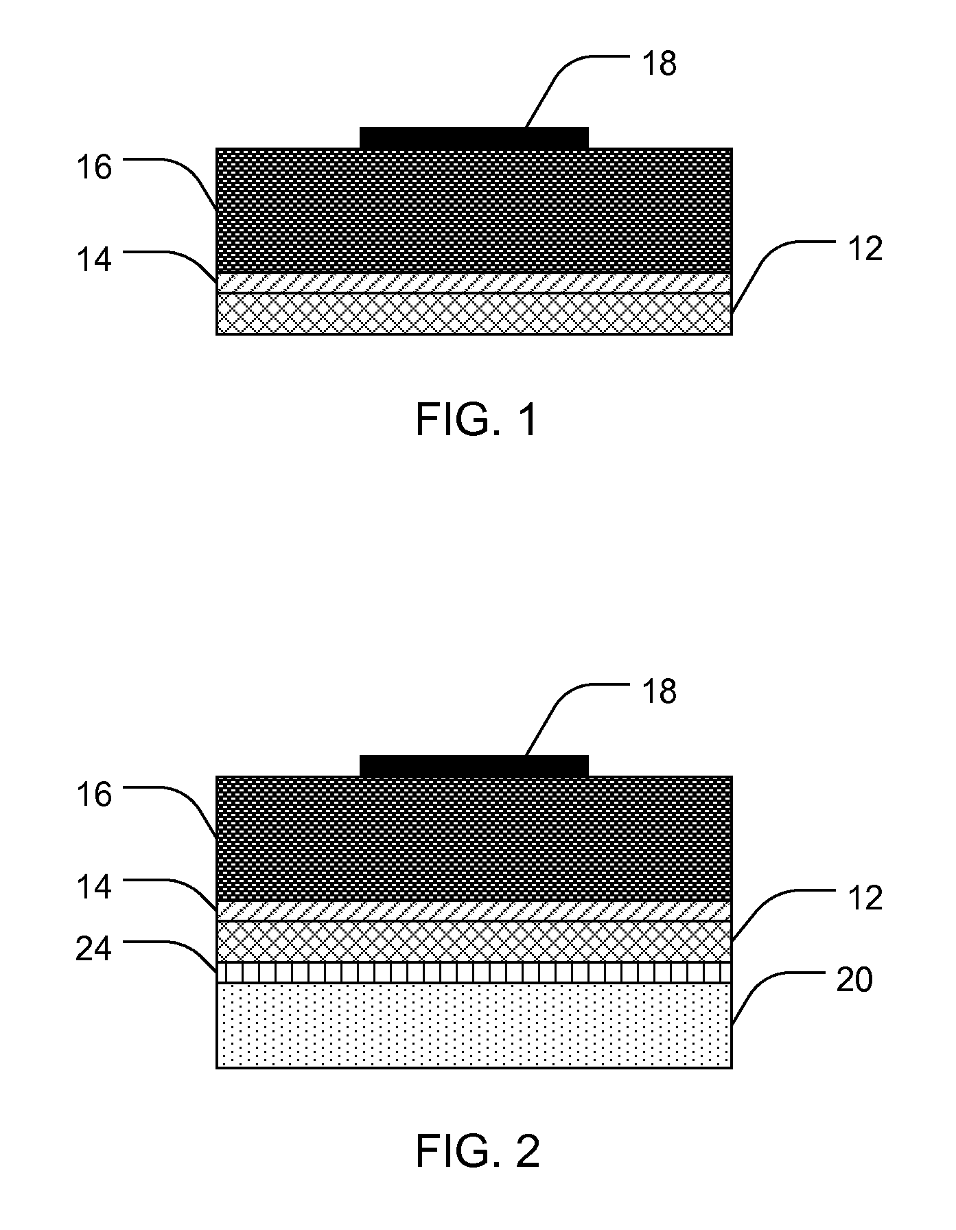
[0077]A semiconductor substrate may be formed as follows:
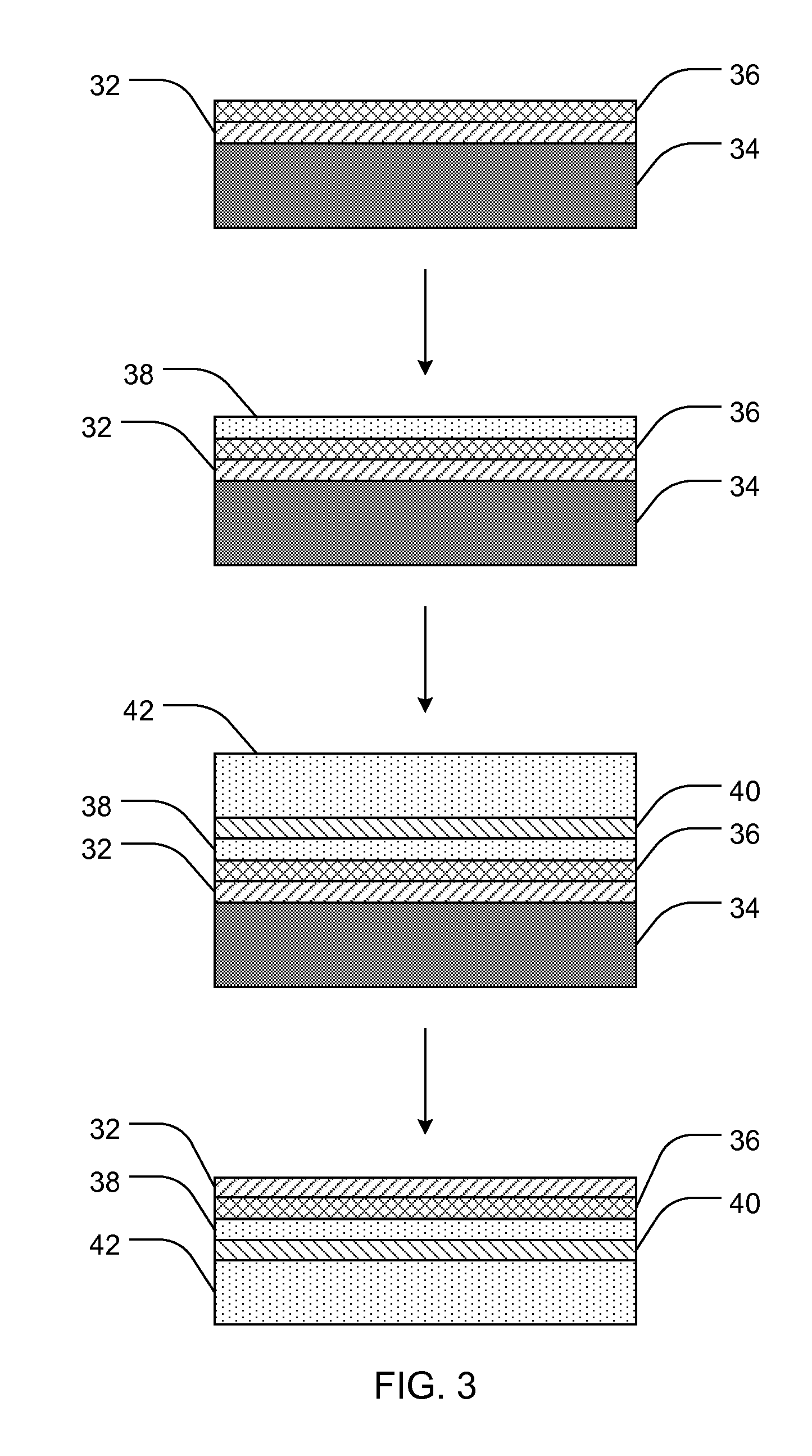
[0078]A single crystal Si wafer is obtained and cleaned by soaking in KOH and ultrasound cleaning with distilled water to remove any non-crystalline Si and foreign debris. A conformal amorphous carbon coating is applied to the cleaned surface of the Si wafer by exposing the wafer to CVD deposition conditions without an applied bias. Following carbonization of the surface, amorphous diamond is deposited for approximately 30 minutes at 800° in 1% CH4 and 99% H2. The amorphous carbon coating is then removed with H2 or F2 treatment for about 60 minutes, at 900°. Removal of the amorphous carbon coating exposes an epitaxial SiC layer that has formed in situ between the Si wafer and the amorphous carbon coating. The thickness of the SiC layer is approximately 10 nm.
[0079]A transparent diamond coating 10 microns thick is then deposited onto the SiC layer by CVD deposition of CH4 for approximately 10 hours. After 10 hours, the CH4 source is then switched to SiH4 for approximately 10 minutes to deposit a 1 micron thick Si layer.
[0080]A Si carrier substrate having a SiO2 surface is wafer bonded to the 1 micron thick Si layer at the SiO2 surface. Following wafer bonding, the single crystal Si wafer is removed to expose the SiC layer by etching with HF+3HNO2+H2O. Further details regarding etching Si materials may be found in U.S. Pat. No. 4,981,818, which is incorporated herein by reference.

Example

Example 2
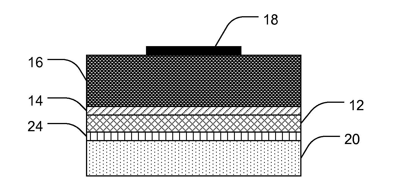
[0081]An LED device may be constructed as follows:
[0082]A semiconductor substrate is obtained as in Example 1. GaN semiconductor layers are deposited onto the exposed SiC layer by MOCVD with GaH3 and NH3 source materials.
[0083]Of course, it is to be understood that the above-described arrangements are only illustrative of the application of the principles of the present invention. Numerous modifications and alternative arrangements may be devised by those skilled in the art without departing from the spirit and scope of the present invention and the appended claims are intended to cover such modifications and arrangements. Thus, while the present invention has been described above with particularity and detail in connection with what is presently deemed to be the most practical and preferred embodiments of the invention, it will be apparent to those of ordinary skill in the art that numerous modifications, including, but not limited to, variations in size, materials, shape, form, function and manner of operation, assembly and use may be made without departing from the principles and concepts set forth herein.

PUM

no PUM

Description & Claims & Application Information

We can also present the details of the Description, Claims and Application information to help users get a comprehensive understanding of the technical details of the patent, such as background art, summary of invention, brief description of drawings, description of embodiments, and other original content. On the other hand, users can also determine the specific scope of protection of the technology through the list of claims; as well as understand the changes in the life cycle of the technology with the presentation of the patent timeline. Login to view more.
Why Eureka
Try Eureka