Magnet assembly

a technology of electromagnets and magnets, applied in the direction of superconducting magnets/coils, magnetic materials, using reradiation, etc., can solve the problems of mri machines being large and expensive devices, preventing the use of mri as a diagnostic tool in applications, and operators having a high degree of skill

Inactive Publication Date: 2010-09-02
EMSCAN
View PDF15 Cites 77 Cited by
  • Summary
  • Abstract
  • Description
  • Claims
  • Application Information

AI Technical Summary

Benefits of technology

[0037]The balancing member may, for example, be in the form of one or more independently supported ferromagnetic rings. However, in one or more preferred embodiments, any or each balancing member is preferably constituted by part of a respective pole piece, i.e., is integral therewith. The pole pieces are ferromagnetic members extending towards each other from the yoke in the vicinity of, preferably passing through the coils. A particularly preferred configuration is wherein any or each pole piece is generally annular when viewed axially, although as will be explained in more detail hereinbelow, the outer circumferential surface and / or inner surface of the annulus may be provided with one or more projections and / or indentations and / or irregularities, preferably continuously around the annulus of the pole piece and / or in the yoke in the vicinity of the pole piece, to provide advantageous properties, in particular with regard to the functioning of the balancing member. Provision of shims to fine-line the magnetic field is also advantageous, e.g., to compensate for lack of axial symmetry in the yoke.

Problems solved by technology

Traditionally, MRI machines are large expensive devices which have to be located in a specially constructed or adapted MRI room and require the operator to have a high degree of skill.
These aspects preclude the use of MRI as a diagnostic tool in applications where space is at a premium and where it would be desirable for the machine to be operated by, for example, nursing staff with only a limited degree of training.
An impediment to such a design is the strong attractive force between the primary field coils and the magnet yoke which may severely limit the achievable performance and practicality of the magnet design.

Method used


Image

  • Magnet assembly
  • Magnet assembly
  • Magnet assembly

Examples


Embodiment Construction

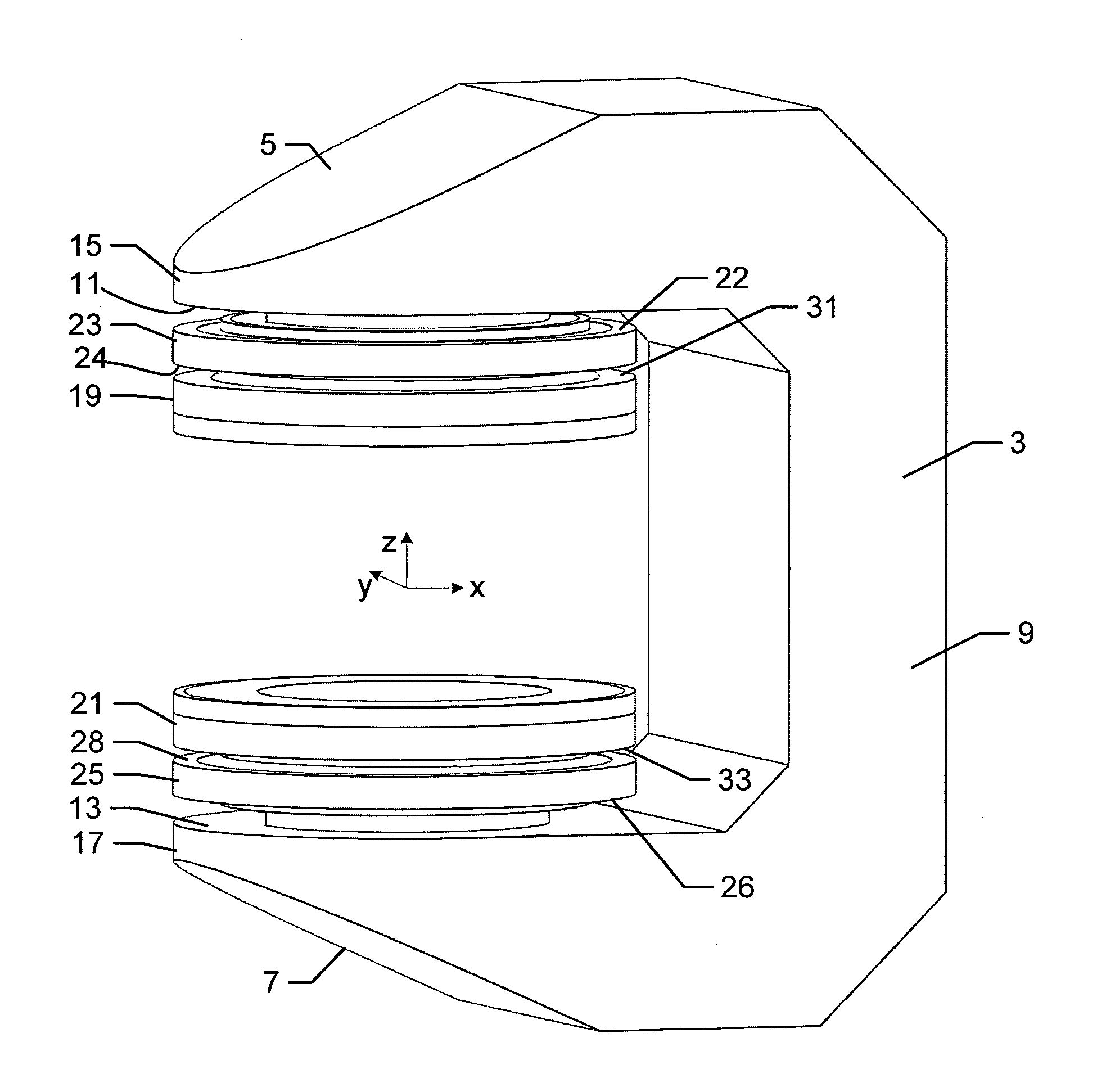
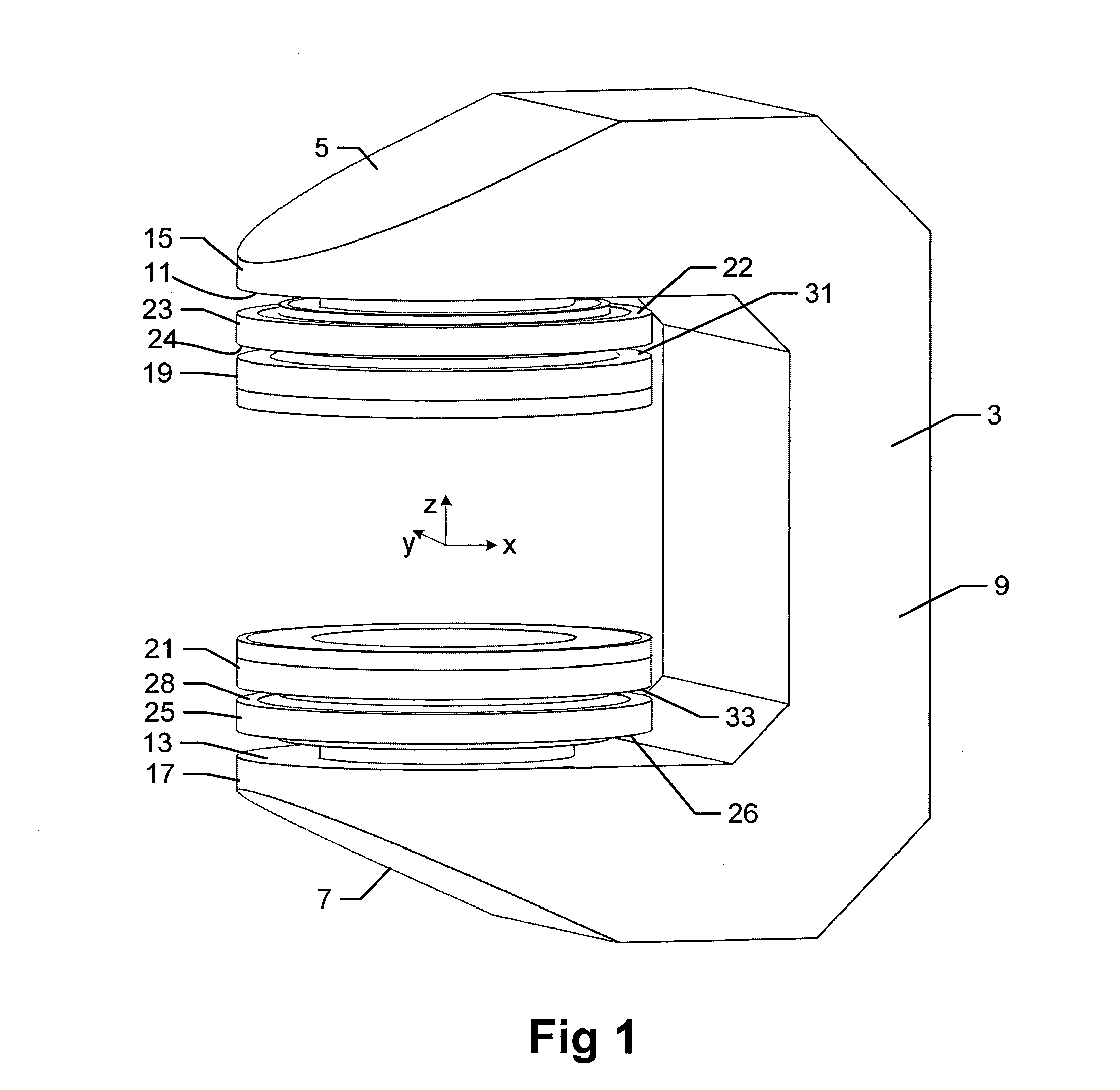
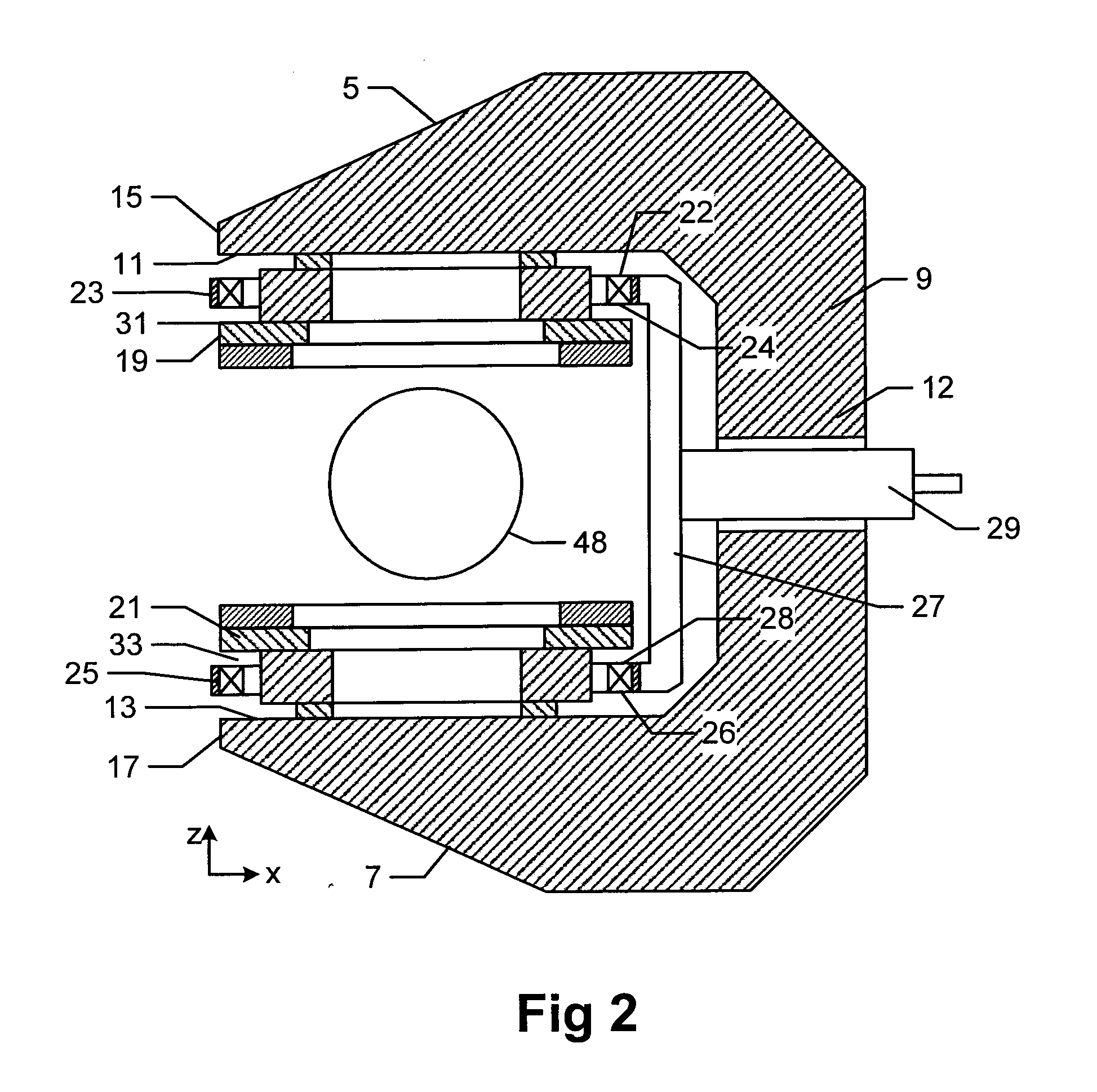
[0051]Referring now to FIG. 1, a magnet assembly 1 comprises a C-shaped steel yoke 3. The yoke itself comprises an upper arm 5, and a lower arm 7 linked by a spine 9. Mounted on the inside surfaces 11, 13 of the free ends 15, 17 of the arms 5, 7, respectively, are upper and lower pole pieces 19, 21, surrounded by respective planar annular drive coils 23, 25. In use, the coils drive magnetic flux around the yoke to produce a substantially uniform magnetic field in the central region between the poles.

[0052]The drive coil 23 has a first side 22 facing the upper yoke arm 5 and a second side 24 facing the other coil 25. Similarly, the drive coil 25 has a first side 26 facing the lower yoke arm 7 and a second side 28 facing the other coil 23.

[0053]Referring to FIGS. 2 and 3, the pair of drive coils 23, 25 carry equal currents current i in the same sense and in series with one another. The coil formers are joined by mechanical supporting member 27 to one side of the coil in the +x directi...


PUM

PropertyMeasurementUnit
weightaaaaaaaaaa
operating temperatureaaaaaaaaaa

Abstract

An electromagnet comprising a ferromagnetic yoke which comprises a yoke. Mutually opposing first and second pole pieces are provided. The first pole piece is provided with a planar coil having a first side facing the yoke and a second side facing the yoke. A balancing member is arranged on the second side of the planar coil to counterbalance the attractive force between the planar coil and the yoke. The other pole piece may also be provided with a corresponding balancing member.

Description

FIELD OF THE INVENTION[0001]The present invention relates to an assembly for an electromagnet, particularly an electromagnet of the kind intended for producing a very high intensity magnetic field such as may be used in a magnetic resonance imaging (MRI) system. However, it is also applicable to other high field applications such as, but not limited to, nuclear magnetic resonance spectrometry (NMR), electron spin resonance spectroscopy (ESR) or general physics laboratory research.BACKGROUND OF THE INVENTION[0002]Traditionally, MRI machines are large expensive devices which have to be located in a specially constructed or adapted MRI room and require the operator to have a high degree of skill. These aspects preclude the use of MRI as a diagnostic tool in applications where space is at a premium and where it would be desirable for the machine to be operated by, for example, nursing staff with only a limited degree of training. An example of such an application would be in an accident...

Claims


Application Information

Patent Timeline
Patent Type & Authority Applications(United States)
IPC IPC(8): G01R33/34H01F7/06
CPCG01R33/383H01F7/06H01F6/04H01F3/10
Inventor MCGINLEY, MARIO VINCENT JOHNRISTIC, MIHAILOBESANT, BOWDEN COLINYOUNG, ROBERT IAN
Owner EMSCAN
Why Eureka
Try Eureka