Digital broadcast reception device

a digital broadcast and reception device technology, applied in the field of digital broadcast reception devices, can solve the problems of weak robustness to a change of transmission paths, difficult reception, and difficult reception in a harsh reception environment, and achieve the effect of reducing the number of antenna switching points and reducing the disconnections of video and audio

Inactive Publication Date: 2010-09-02
PANASONIC CORP
View PDF11 Cites 36 Cited by
  • Summary
  • Abstract
  • Description
  • Claims
  • Application Information

AI Technical Summary

Benefits of technology

[0012]A digital broadcast reception device includes a broadcast wave reception antenna for receiving a broadcast signal; a station selection demodulation unit for selecting and demodulating the broadcast signal received by the broadcast wave reception antenna, and distributing and outputting a signal for each hierarchy; and a first decoding unit for decoding one signal of the plurality of demodulated signals output from the station selection demodulation unit. Furthermore, the digital broadcast reception device includes a second decoding unit for decoding another signal of the plurality of demodulated signals output from the station selection demodulation unit; an output switching unit for switching and outputting the signals output from the first decoding unit and the second decoding unit; and a position information detection unit for detecting position information and outputting a position information signal. Furthermore, the digital broadcast reception device includes a movement direction detection unit for detecting a movement direction of the digital broadcast reception device based on the position information signal output from the position information detection unit and outputting a movement direction information signal; and a database holding unit for holding reception quality information in which the position information signal is related to reception quality at a corresponding position. Furthermore, the digital broadcast reception device includes a switching point calculation unit for calculating a hierarchy switching point based on the position information signal output from the position information detection unit, the movement direction information signal output from the movement direction detection unit and the reception quality information stored in the database holding unit, and outputting a switching request signal to the output switching unit. Then, the switching point calculation unit controls the output switching unit based on the reception quality information, the movement direction information signal and the position information signal, thereby controlling so that generation of the hierarchy switching during movement is reduced.
[0016]With such a configuration, the digital broadcast reception device can carry out a diversity synthesis by using the plurality of broadcast wave reception antennas and station selection demodulation units. The plurality of station selection demodulation units can select different physical channels, and thereby channel scanning and obtaining other programs of other channels can be carried out. Then, the switching unit firstly calculates a movement route to be predicted by using the position information signal output from the position information detection unit and the movement direction information signal output from the movement direction detection unit; and then, reads out the reception quality information on the calculated movement route from the database holding unit. In a zone on the movement route in which an excellent reception can be carried out by using one broadcast wave reception antenna and one station selection demodulation unit, background processing is carried out by using another broadcast wave reception antenna and another station selection demodulation unit. Furthermore, before reaching a zone in which excellent reception cannot be carried out by one broadcast wave reception antenna and one station selection demodulation unit, the background processing is stopped and both broadcast wave reception antennas and station selection demodulation units are used for viewing and listening so as to secure the reception quality. In other words, by carrying out antenna switching between one system of received signal composed of one broadcast wave reception antenna and one station selection demodulation unit and a plurality of systems of received signals composed of a plurality of broadcast wave reception antennas and a plurality of station selection demodulation units, the reception quality is secured.
[0018]Therefore, it is possible to realize a digital broadcast reception device in which when digital broadcast is received during movement, antenna switching points are predicted and the number of antenna switching points is reduced, thereby reducing disconnections of video and audio.
[0019]Furthermore, it is possible to realize a digital broadcast reception device in which when digital broadcast is received during movement, the digital reception device can perform a necessary background processing without deteriorating the reception quality of the channel for viewing and listening.

Problems solved by technology

However, in the 64QAM modulation format, robustness to a change of a transmission path is weak and reception is difficult in a weak electric field.
Therefore, reception is difficult in a harsh reception environment such as reception in a mobile body.
However, since such a method carries out a hierarchy switching after it determines values such as an electric field strength, a block noise, and BER, it cannot respond to a rapid change of a reception environment, so that video and audio having a poor reception quality may be displayed before hierarchy stitching is carried out.
In addition, during movement on a route whose reception environment is changed relatively drastically, hierarchy switching occurs frequently, which may make a user feel uncomfortable.
However, since an appropriate switching holding time is different depending upon a running position and a receiving state, it has been difficult to constantly perform appropriate switching in various reception environments.
However, even in a position in which a satisfactory reception quality cannot be secured unless four branches are used, during processing using one branch in the background, only reception quality corresponding to three branches can be obtained.
Even when deterioration of the reception quality is detected and reception can be changed to 4-branch reception, it is not possible to carry out a rapid response to the change of a reception environment.

Method used


Image

  • Digital broadcast reception device
  • Digital broadcast reception device
  • Digital broadcast reception device

Examples


first exemplary embodiment

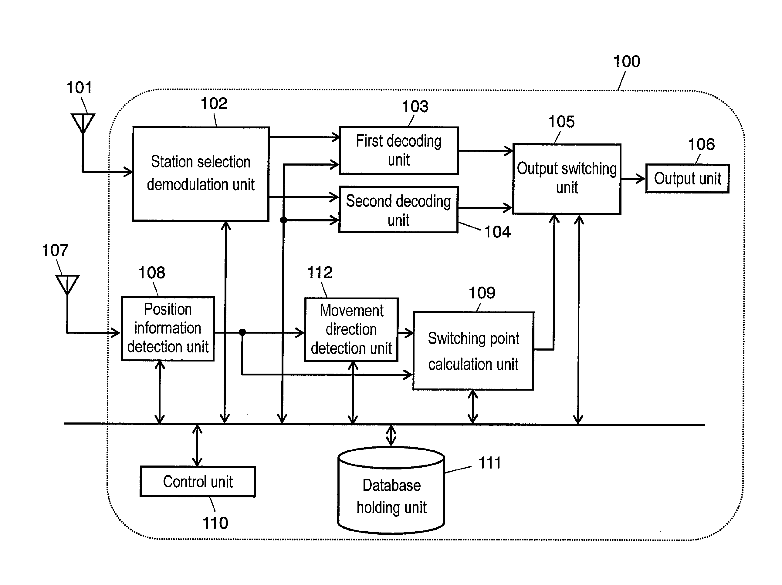
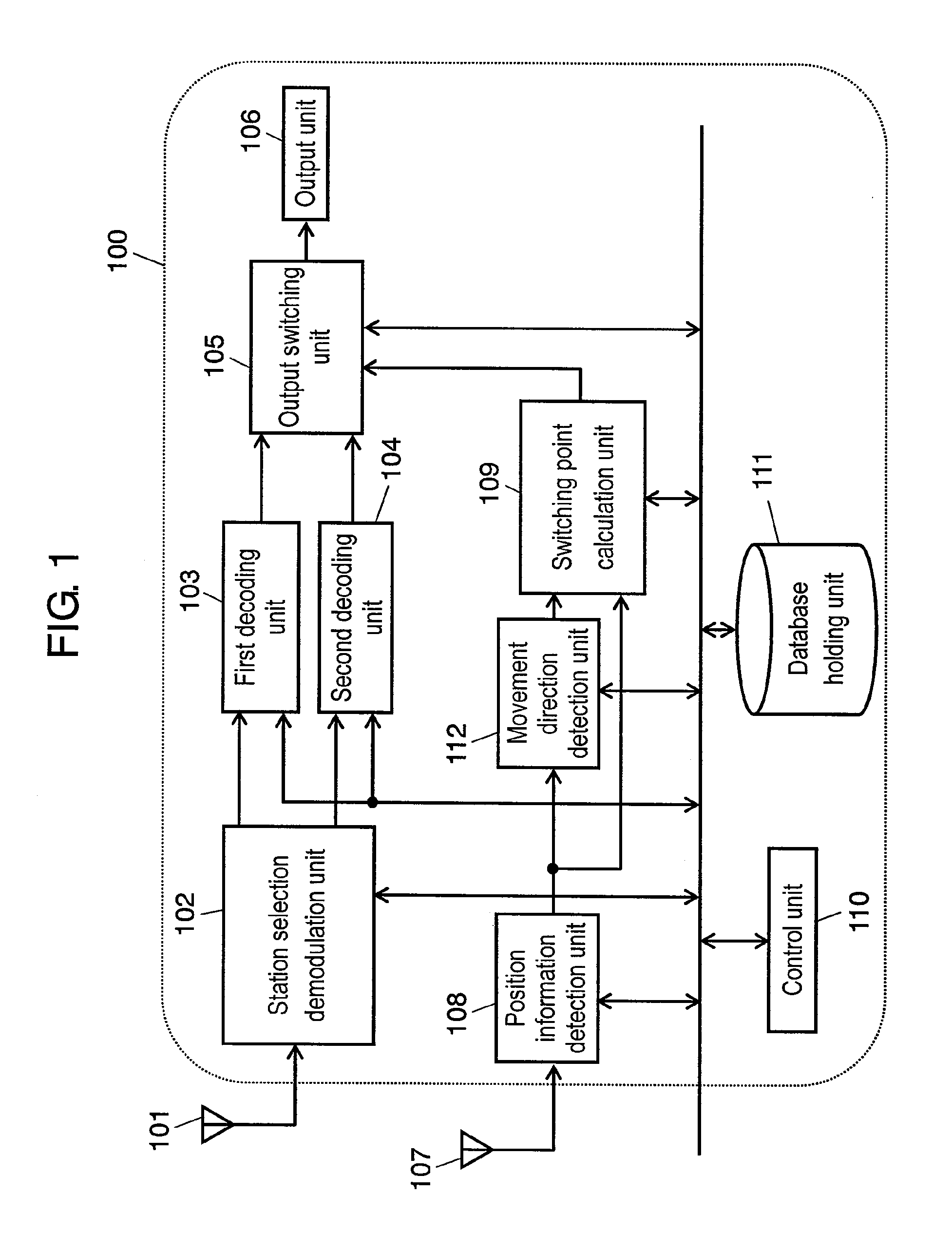
[0077]FIG. 1 is a block diagram showing a configuration of digital broadcast reception device 100 in this exemplary embodiment. Digital broadcast reception device 100 shown in FIG. 1 includes first antenna 101 as a broadcast wave reception antenna, station selection demodulation unit 102, first decoding unit 103, second decoding unit 104, output switching unit 105 and output unit 106. Furthermore, digital broadcast reception device 100 includes second antenna 107 as a reference position information reception antenna, position information detection unit 108, movement direction detection unit 112, switching point calculation unit 109, control unit 110, and database holding unit 111.

[0078]Station selection demodulation unit 102 receives an input of an RF signal output from first antenna 101 including a UHF reception antenna and the like, which receives a terrestrial digital broadcast wave by digital broadcast services such as terrestrial digital broadcast services; and selects and demo...

second exemplary embodiment

[0124]FIG. 12 is a block diagram showing a configuration of digital broadcast reception device 200 in accordance with this exemplary embodiment. Digital broadcast reception device 200 shown in FIG. 12 includes first antenna 201 and third antenna 203 as a plurality of broadcast wave reception antennas for receiving a broadcast signal; and first and second station selection demodulation units 202 and 204 as a plurality of station selection demodulation units. Furthermore, digital broadcast reception device 200 includes synthesizing and distributing unit 205, first transport decoding unit 206, second transport decoding unit 207, AV decoding unit 208, and output unit 209. Furthermore, digital broadcast reception device 200 includes second antenna 210 as a reference position information reception antenna, position information detection unit 211, movement direction detection unit 212, switching unit 213, database holding unit 214 and control unit 215.

[0125]The thus configured digital broa...


PUM


Abstract

A digital broadcast reception device mounted on a mobile body includes a position information detection unit for detecting the position of the digital broadcast reception device, a database holding unit for storing reception quality of the digital broadcast in advance, a switching point calculation unit for obtaining a hierarchy switching point, and output switching unit for performing a hierarchy switching. The digital broadcast reception device acquires the hierarchy switching frequency generated during movement in advance based on reception quality information previously stored in the database holding unit, and controls the hierarchy switching so as to reduce the switching frequency, thereby reducing disconnections of video and audio.

Description

[0001]This application is a U.S. National Phase Application of PCT International Application PCT / JP2007 / 060114.TECHNICAL FIELD[0002]The present invention relates to a mobile digital broadcast reception device. More particularly, it relates to a technology for calculating a reception situation during movement in advance and switching a hierarchy to be received.BACKGROUND ART[0003]In terrestrial digital broadcast1services, a transmission band of one physical channel is divided into 13 segments for example. Therefore, signals of different modulation formats can be multiplexed in one physical channel. For example, 12 segments of 13 segments are transmitted in a 64QAM modulation format for fixed reception, and at the same time, one segment is transmitted in a QPSK modulation format for mobile reception. Therefore, it is possible to select a hierarchy to be received in accordance with a reception environment and a receiving terminal at the side of the receiving terminal. For example, in t...

Claims


Application Information

Patent Timeline
Patent Type & Authority Applications(United States)
IPC IPC(8): H04L27/06H04B1/16H04B7/08H04N5/44H04N7/173
CPCH04H20/42H04H20/57H04H40/27H04H60/51H04H60/65H04N21/4524H04N21/41407H04N21/42202H04N21/4382H04N21/44016H04N5/4401H04N21/426
Inventor YAMAMOTO, KOHSUKETOIYAMA, KEIICHI
Owner PANASONIC CORP
Why Eureka
Try Eureka