Devices, systems, and methods for removing targeted lesions from vessels

a technology of targeted lesions and devices, applied in the field of devices, systems and methods for removing stenotic lesions from vessels, can solve the problems of inability to predict the progression rate of an individual patient, heart attack, and difficult to distinguish patients with low cardiac output, so as to facilitate operation control and facilitate one or more fluid injections.

Active Publication Date: 2010-09-02
3DT HLDG
View PDF67 Cites 231 Cited by
  • Summary
  • Abstract
  • Description
  • Claims
  • Application Information

AI Technical Summary

Benefits of technology

[0025]In at least one embodiment of a device for removing a stenotic lesion from a vessel of the present disclosure, the device further comprises at least one suction / infusion port in communication with at least one device lumen, the suction / infusion port operable to facilitate one or more fluid injections into the lumen of the luminal organ, and at least one fluid delivery source operably coupled to the at least device lumen, whereby one or more fluids may be injected from the at least one fluid delivery source through the at least one device lumen, through the at least one suction / infusion port, and into the lumen of the luminal organ. In another embodiment, the device further comprises a current source in communication with the two excitation electrodes, said current source operable to supply current to the two excitation electrodes to enable measurement of at least one conductance value, thereby enabling calculation of a luminal size parameter. In yet another embodiment, the device further comprises a data acquisition and processing system operably coupled to the device, the data acquisition and processing system operable to receive conductance data from the device to calculate at least one luminal parameter based upon said conductance data and to display the calculated at least one luminal parameter to facilitate operational control of the at least one treatment portion of the device.

Problems solved by technology

It is likely to produce angina pectoris, heart attack or both.
Although it appears that progression of AS can be more rapid in patients with degenerative calcific disease than in those with congenital or rheumatic disease, it is not possible to predict the rate of progression in an individual patient.
Problems with Current Aortic Valve Area Measurements
Such patients can be difficult to distinguish from those with low cardiac output and only mild to moderate AS.
Although valve resistance is less sensitive to flow than valve area, resistance calculations have not been proved to be substantially better than valve area calculations.
There are many other limitations in estimating aortic valve area in patients with aortic stenosis using echocardiography and cardiac catheterization.
Accurate measurement of the aortic valve area in patients with aortic stenosis can be difficult in the setting of low cardiac output or concomitant aortic or mitral regurgitations.
Furthermore, because of the dependence of aortic valve area calculation on cardiac output, any under or overestimation of cardiac output will cause inaccurate measurement of valve area.
Falsely measured aortic valve area could cause inappropriate aortic valve surgery in patients who do not need it.

Method used


Image

  • Devices, systems, and methods for removing targeted lesions from vessels
  • Devices, systems, and methods for removing targeted lesions from vessels
  • Devices, systems, and methods for removing targeted lesions from vessels

Examples


Embodiment Construction

[0064]Reference will now be made to the embodiments illustrated in the drawings and specific language will be used to describe the same. It will nevertheless be understood that no limitation of scope is intended by the description of these embodiments.

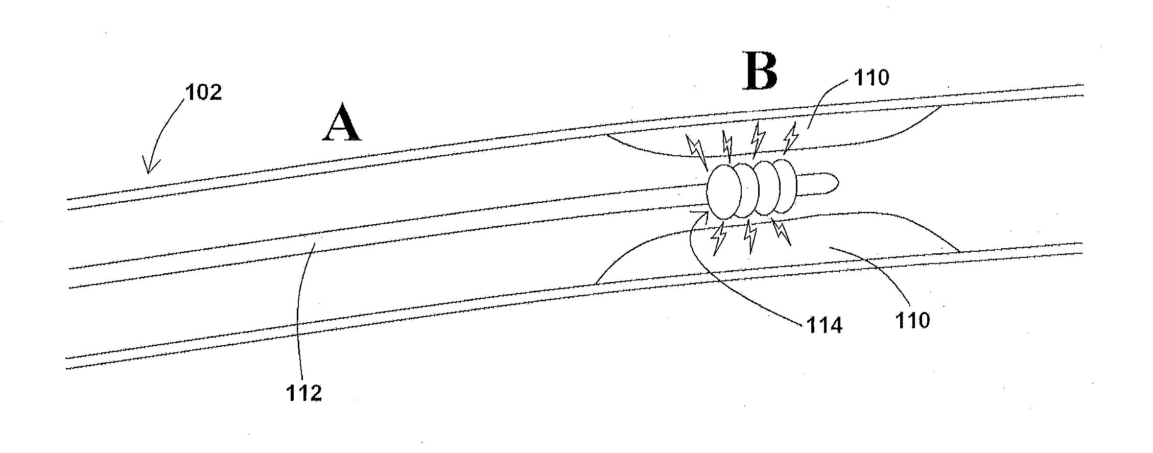
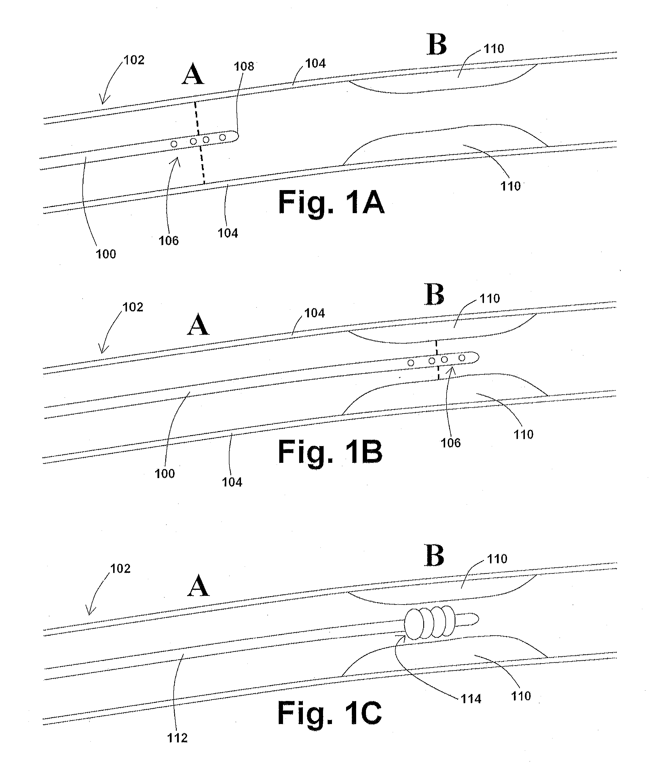
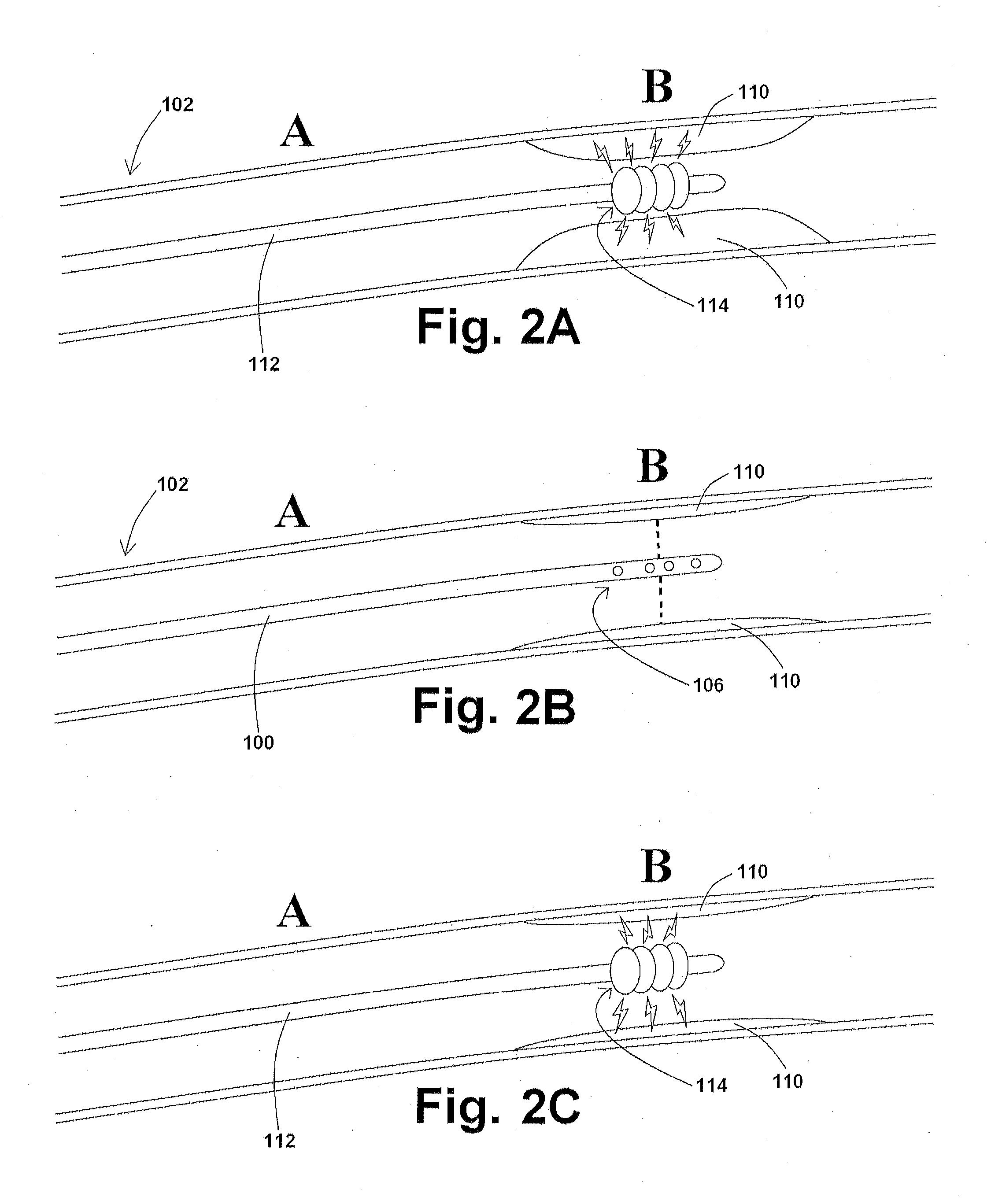
[0065]In at least one embodiment of a method for removing a stenotic lesion of a vessel, the method comprises the steps of measuring at least two luminal parameters, determining a preferred luminal size parameter, and operating a treatment device to increase at least one of the luminal parameters.

[0066]In at least one exemplary method for removing a stenotic lesion of a vessel, the method comprises the steps of measuring a first luminal size parameter at a first location within a vessel lumen, measuring a second luminal size parameter at a second location within the vessel lumen, determining a preferred second luminal size parameter based upon the first luminal size parameter and the second luminal size parameter, and positioning a tre...


PUM


Abstract

Devices, systems, and methods for removing targeted lesions from vessels. In at least one embodiment of a device for removing a stenotic lesion from a vessel, the device comprises a sizing portion capable of measuring a luminal size parameter when at least part of the device is positioned within a lumen of a luminal organ, a typing portion, wherein at least part of the at least one typing portion is capable of physically touching a portion of the luminal organ or a structure therein, and a treatment portion capable of removing at least part of a stenotic lesion from the luminal organ.

Description

PRIORITY[0001]This U.S. Utility patent application is a continuation-in-part application of, and claims priority to, copending U.S. patent application Ser. No. 12 / 428,656, filed Apr. 23, 2009, which is a continuation-in-part application of, and claims priority to, copending U.S. patent application Ser. No. 12 / 098,242, filed Apr. 4, 2008, which is a continuation-in-part application of, and claims priority to, copending U.S. patent application Ser. No. 11 / 891,981, filed Aug. 14, 2007, which is a divisional application of, and claims priority to, U.S. patent application Ser. No. 10 / 782,149, filed Feb. 19, 2004, which issued as U.S. Pat. No. 7,454,244 on Nov. 18, 2008, which claims priority to U.S. Provisional Patent Application Ser. No. 60 / 449,266, filed Feb. 21, 2003, to U.S. Provisional Patent Application Ser. No. 60 / 493,145, filed Aug. 7, 2003, and to U.S. Provisional Patent Application Ser. No. 60 / 502,139, filed Sep. 11, 2003. The contents of each of these applications are hereby i...

Claims


Application Information

Patent Timeline
Patent Type & Authority Applications(United States)
IPC IPC(8): A61B17/22
CPCA61B5/053A61M2025/0002A61B5/1076A61B5/417A61B17/22004A61B17/320725A61B17/320758A61B18/02A61B18/24A61B19/46A61B2017/00026A61B2017/00084A61B2017/22044A61B2017/22061A61B2018/0022A61B2018/0212A61B2019/461A61F2/958A61M25/1018A61B5/0538A61B90/06A61B2090/061A61M25/10188A61M25/10184A61B5/4836A61B5/0036A61B5/01A61B17/22A61B18/245
Inventor KASSAB, GHASSAN S.
Owner 3DT HLDG
Why Eureka
Try Eureka